HP ProBook 430 HP ProBook 430 G1 Notebook PC Maintenance and Service Guide - Page 58
WLAN/Bluetooth combo card
 |
View all HP ProBook 430 manuals
Add to My Manuals
Save this manual to your list of manuals |
Page 58 highlights
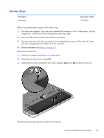
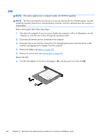
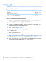
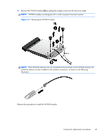
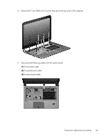
WLAN/Bluetooth combo card The computer uses a card that provides both WLAN and Bluetooth functionality. CAUTION: The WLAN module and the WWAN module are not interchangeable. Description Realtek RTL8188EE 802.11bgn Wi-Fi Adapter Mediatek MT7630E 802.11bgn Wi-Fi Adapter and Mediatek Bluetooth 4.0 Adapter Intel Dual Band Wireless-N 7260AN 802.11 a/b/g/n 2x2 WiFi + BT4.0 Broadcom BCM943228HMB 802.11abgn 2x2 Wi-Fi + BT 4.0 Combo Adapter Atheros AR9485 802.11b/g/n 1x1 WiFi Adapter Atheros AR9565 802.11bgn 1x1 WiFi + BT4.0 combo Adapter Spare part number 709848-001 710418-001 717381-001 731550-001 675794-001 690019-001 Before removing the WLAN module, follow these steps: 1. Shut down the computer. If you are unsure whether the computer is off or in Hibernation, turn the computer on, and then shut it down through the operating system. 2. Disconnect all external devices connected to the computer. 3. Disconnect the power from the computer by first unplugging the power cord from the AC outlet, and then unplugging the AC adapter from the computer. 4. Remove the battery (see Battery on page 35). 5. Remove the service door (see Service door on page 43). Remove the WLAN module: 1. Position the computer upside-down. 2. Disconnect the WLAN antenna cables (1) from the terminals on the WLAN module. NOTE: The WLAN antenna cable labeled "1" connects to the WLAN module "Main" terminal labeled "1". The WLAN antenna cable labeled "2" connects to the WLAN module "Aux" terminal labeled "2". If the computer is equipped with an 802.11a/b/g/n WLAN module, the yellow WLAN antenna cable connects to the middle terminal on the WLAN module. 3. Remove the two Phillips PM2.5×3.0 screws (2) that secure the WLAN module to the computer. (The edge of the module opposite the slot rises away from the computer.) 48 Chapter 5 Removal and replacement procedures for Customer Self-Repair parts
-
 1
1 -
2
-
3
-
4
-
5
-
6
-
7
-
8
-
9
-
10
-
11
-
12
-
13
-
14
-
15
-
16
-
17
-
18
-
19
-
20
-
21
-
22
-
23
-
24
-
25
-
26
-
27
-
28
-
29
-
30
-
31
-
32
-
33
-
34
-
35
-
36
-
37
-
38
-
39
-
40
-
41
-
42
-
43
-
44
-
45
-
46
-
47
-
48
-
49
-
50
-
51
-
52
-
 53
53 -
 54
54 -
 55
55 -
 56
56 -
 57
57 -
 58
58 -
 59
59 -
 60
60 -
 61
61 -
 62
62 -
 63
63 -
64
-
65
-
66
-
67
-
68
-
69
-
70
-
71
-
72
-
73
-
74
-
75
-
76
-
77
-
78
-
79
-
80
-
81
-
82
-
83
-
84
-
85
-
86
-
87
-
88
-
89
-
90
-
91
-
92
-
93
-
94
-
95
-
96
-
97
-
98
-
99
-
100
-
101
-
102
-
103
-
104
-
105
-
106
-
107
-
108
-
109
-
110
-
111
-
112
-
113
-
114
-
115
-
116
-
117
-
118
-
119
-
120
-
121
-
122
-
123
-
124
-
125
-
126
-
127
-
128
-
129
-
130
-
131
-
132
-
133
-
134
-
135
-
136
-
137
-
138
-
139
 |
 |