HP ProBook 430 HP ProBook 430 G1 Notebook PC Maintenance and Service Guide - Page 61
rear rubber screw covers, Remove the top cover
 |
View all HP ProBook 430 manuals
Add to My Manuals
Save this manual to your list of manuals |
Page 61 highlights
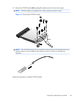
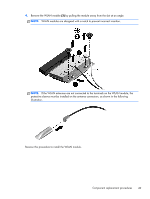
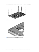
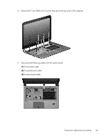
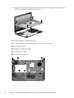
3. Disconnect the power from the computer by first unplugging the power cord from the AC outlet, and then unplugging the AC adapter from the computer. 4. Remove the battery (see Battery on page 35). 5. Remove the following components: a. Service door (see Service door on page 43). b. Keyboard (see Keyboard on page 37) c. Hard drive (see Hard drive on page 40) Remove the top cover: 1. Position the computer upside-down with the front toward you. 2. Remove the following screw covers from atop the screws on the bottom of the computer: (1) 2 rear rubber screw covers (2) 2 middle rubber screw covers (3) 2 front rubber screw covers NOTE: Rubber screw covers are available in the Rubber/Plastics Kit, spare part number 727762-001. Component replacement procedures 51
-
 1
1 -
2
-
3
-
4
-
5
-
6
-
7
-
8
-
9
-
10
-
11
-
12
-
13
-
14
-
15
-
16
-
17
-
18
-
19
-
20
-
21
-
22
-
23
-
24
-
25
-
26
-
27
-
28
-
29
-
30
-
31
-
32
-
33
-
34
-
35
-
36
-
37
-
38
-
39
-
40
-
41
-
42
-
43
-
44
-
45
-
46
-
47
-
48
-
49
-
50
-
51
-
52
-
53
-
54
-
55
-
 56
56 -
 57
57 -
 58
58 -
 59
59 -
 60
60 -
 61
61 -
 62
62 -
 63
63 -
 64
64 -
 65
65 -
 66
66 -
67
-
68
-
69
-
70
-
71
-
72
-
73
-
74
-
75
-
76
-
77
-
78
-
79
-
80
-
81
-
82
-
83
-
84
-
85
-
86
-
87
-
88
-
89
-
90
-
91
-
92
-
93
-
94
-
95
-
96
-
97
-
98
-
99
-
100
-
101
-
102
-
103
-
104
-
105
-
106
-
107
-
108
-
109
-
110
-
111
-
112
-
113
-
114
-
115
-
116
-
117
-
118
-
119
-
120
-
121
-
122
-
123
-
124
-
125
-
126
-
127
-
128
-
129
-
130
-
131
-
132
-
133
-
134
-
135
-
136
-
137
-
138
-
139
 |
 |