HP ProBook 430 HP ProBook 430 G1 Notebook PC Maintenance and Service Guide - Page 77
atop the module, If it is necessary to replace the webcam module from the display enclosure
 |
View all HP ProBook 430 manuals
Add to My Manuals
Save this manual to your list of manuals |
Page 77 highlights
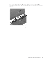
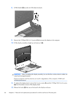
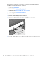
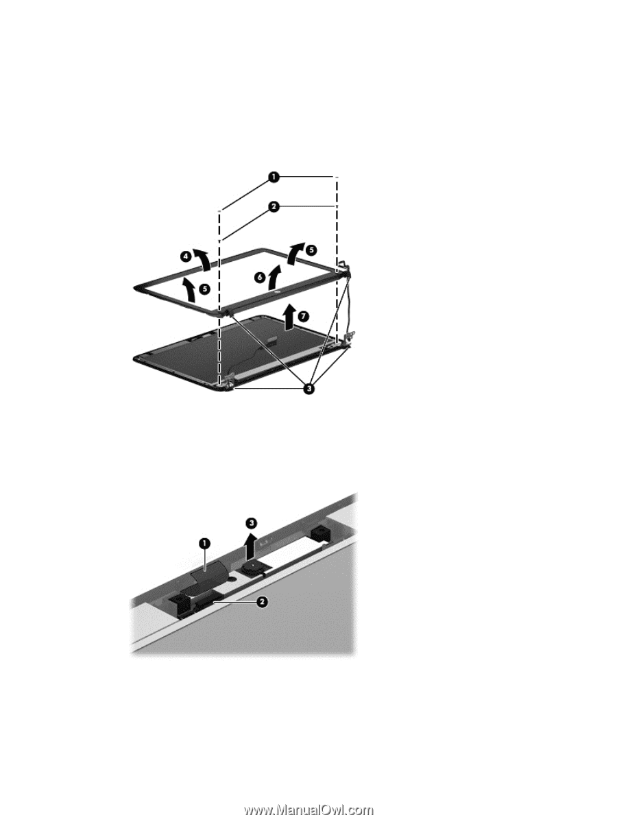
13. Flex the top (4) of the bezel, the inside edges of the left and right sides (5), and then the bottom (6) of the bezel until it disengages from the display enclosure. 14. Remove the display bezel (7). The bezel is available using spare part number 731994-001. Screw covers are available in the Rubber/Plastics Kit, spare part number 727762-001. 15. If it is necessary to replace the webcam module from the display enclosure, remove the tape from atop the module (1), disconnect the cable from the module (2), and then gently pull the module away from the double-sided tape on the display enclosure (3). The webcam module is available using spare part number 721543-001. Component replacement procedures 67
-
 1
1 -
2
-
3
-
4
-
5
-
6
-
7
-
8
-
9
-
10
-
11
-
12
-
13
-
14
-
15
-
16
-
17
-
18
-
19
-
20
-
21
-
22
-
23
-
24
-
25
-
26
-
27
-
28
-
29
-
30
-
31
-
32
-
33
-
34
-
35
-
36
-
37
-
38
-
39
-
40
-
41
-
42
-
43
-
44
-
45
-
46
-
47
-
48
-
49
-
50
-
51
-
52
-
53
-
54
-
55
-
56
-
57
-
58
-
59
-
60
-
61
-
62
-
63
-
64
-
65
-
66
-
67
-
68
-
69
-
70
-
71
-
 72
72 -
 73
73 -
 74
74 -
 75
75 -
 76
76 -
 77
77 -
 78
78 -
 79
79 -
 80
80 -
 81
81 -
 82
82 -
83
-
84
-
85
-
86
-
87
-
88
-
89
-
90
-
91
-
92
-
93
-
94
-
95
-
96
-
97
-
98
-
99
-
100
-
101
-
102
-
103
-
104
-
105
-
106
-
107
-
108
-
109
-
110
-
111
-
112
-
113
-
114
-
115
-
116
-
117
-
118
-
119
-
120
-
121
-
122
-
123
-
124
-
125
-
126
-
127
-
128
-
129
-
130
-
131
-
132
-
133
-
134
-
135
-
136
-
137
-
138
-
139
 |
 |
13.
Flex the top
(4)
of the bezel, the inside edges of the left and right sides
(5)
, and then the bottom
(6)
of the bezel until it disengages from the display enclosure.
14.
Remove the display bezel
(7)
.
The bezel is available using spare part number 731994-001.
Screw covers are available in the Rubber/Plastics Kit, spare part number 727762-001.
15.
If it is necessary to replace the webcam module from the display enclosure, remove the tape from
atop the module
(1)
, disconnect the cable from the module
(2)
, and then gently pull the module
away from the double-sided tape on the display enclosure
(3)
.
The webcam module is available using spare part number 721543-001.
Component replacement procedures
67