HP ProBook 430 HP ProBook 430 G1 Notebook PC Maintenance and Service Guide - Page 75
Remove the 2 Phillips PM2.0×4.0 screws, from the routing path on the top of the base
 |
View all HP ProBook 430 manuals
Add to My Manuals
Save this manual to your list of manuals |
Page 75 highlights
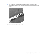
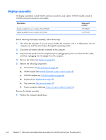
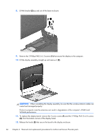
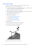
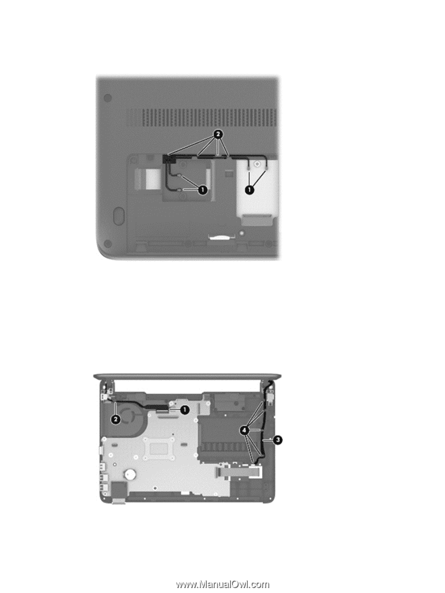
2. Remove the WLAN and WWAN antennas (1) from the routing path (2) on the bottom of the computer. 3. Pull the antennas through the hole that leads to the top of the computer. 4. Position the computer upright and open the computer as far as possible. 5. Disconnect the display cable (1) from the system board and remove the cable from the routing path in the base enclosure (2). 6. Remove the WLAN and WWAN antennas (3) from the routing path on the top of the base enclosure (4), and pull the antenna cables through the hole that routes to the bottom of the computer. 7. Remove the 2 Phillips PM2.0×4.0 screws (1) that secure the power connector bracket to the computer. Component replacement procedures 65
-
 1
1 -
2
-
3
-
4
-
5
-
6
-
7
-
8
-
9
-
10
-
11
-
12
-
13
-
14
-
15
-
16
-
17
-
18
-
19
-
20
-
21
-
22
-
23
-
24
-
25
-
26
-
27
-
28
-
29
-
30
-
31
-
32
-
33
-
34
-
35
-
36
-
37
-
38
-
39
-
40
-
41
-
42
-
43
-
44
-
45
-
46
-
47
-
48
-
49
-
50
-
51
-
52
-
53
-
54
-
55
-
56
-
57
-
58
-
59
-
60
-
61
-
62
-
63
-
64
-
65
-
66
-
67
-
68
-
69
-
 70
70 -
 71
71 -
 72
72 -
 73
73 -
 74
74 -
 75
75 -
 76
76 -
 77
77 -
 78
78 -
 79
79 -
 80
80 -
81
-
82
-
83
-
84
-
85
-
86
-
87
-
88
-
89
-
90
-
91
-
92
-
93
-
94
-
95
-
96
-
97
-
98
-
99
-
100
-
101
-
102
-
103
-
104
-
105
-
106
-
107
-
108
-
109
-
110
-
111
-
112
-
113
-
114
-
115
-
116
-
117
-
118
-
119
-
120
-
121
-
122
-
123
-
124
-
125
-
126
-
127
-
128
-
129
-
130
-
131
-
132
-
133
-
134
-
135
-
136
-
137
-
138
-
139
 |
 |
2.
Remove the WLAN and WWAN antennas
(1)
from the routing path
(2)
on the bottom of the
computer.
3.
Pull the antennas through the hole that leads to the top of the computer.
4.
Position the computer upright and open the computer as far as possible.
5.
Disconnect the display cable
(1)
from the system board and remove the cable from the routing
path in the base enclosure
(2)
.
6.
Remove the WLAN and WWAN antennas
(3)
from the routing path on the top of the base
enclosure
(4)
, and pull the antenna cables through the hole that routes to the bottom of the
computer.
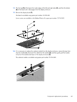
7.
Remove the 2 Phillips PM2.0×4.0 screws
(1)
that secure the power connector bracket to the
computer.
Component replacement procedures
65