HP ProBook 4525s HP ProBook 4525s Notebook PC - Maintenance and Service Guide
HP ProBook 4525s - Notebook PC Manual
 |
View all HP ProBook 4525s manuals
Add to My Manuals
Save this manual to your list of manuals |
HP ProBook 4525s manual content summary:
- HP ProBook 4525s | HP ProBook 4525s Notebook PC - Maintenance and Service Guide - Page 1
HP ProBook 4525s Notebook PC Maintenance and Service Guide - HP ProBook 4525s | HP ProBook 4525s Notebook PC - Maintenance and Service Guide - Page 2
in the express warranty statements accompanying such products and services. Nothing herein should be construed as constituting an additional warranty. HP shall not be liable for technical or editorial errors or omissions contained herein. First Edition: May 2010 Document Part Number: 598083-001 - HP ProBook 4525s | HP ProBook 4525s Notebook PC - Maintenance and Service Guide - Page 3
Safety warning notice WARNING! To reduce the possibility of heat-related injuries or of overheating the computer, do not place the computer directly on your lap or obstruct the computer air vents. Use the computer only on a hard, flat surface. Do not allow another hard surface, such as an adjoining - HP ProBook 4525s | HP ProBook 4525s Notebook PC - Maintenance and Service Guide - Page 4
iv Safety warning notice - HP ProBook 4525s | HP ProBook 4525s Notebook PC - Maintenance and Service Guide - Page 5
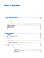
15 Bottom components ...16 Display ...16 Wireless antennas ...18 Additional hardware components 19 3 Illustrated parts catalog 20 Service part number listing 33 4 Removal and replacement procedures 38 Preliminary replacement requirements 38 Tools required ...38 Service considerations 38 - HP ProBook 4525s | HP ProBook 4525s Notebook PC - Maintenance and Service Guide - Page 6
guidelines 41 Equipment guidelines 42 Component replacement procedures 43 Service tag ...43 Computer feet ...44 Battery ...45 Processor ...65 Palm rest ...67 Hard drive ...69 Display assembly on computers with 15.6-in displays 71 Top cover ...77 RTC battery ...80 Bluetooth module ...82 Modem - HP ProBook 4525s | HP ProBook 4525s Notebook PC - Maintenance and Service Guide - Page 7
...105 Computer specifications ...105 15.6-in display specifications 107 Hard drive specifications ...108 DVD-ROM Drive specifications 109 DVD±RW Double-Layer Combo Drive specifications 110 Blu-ray Disc ROM Drive with SuperMulti DVD±R/RW Double-Layer specifications 111 7 Backup and - HP ProBook 4525s | HP ProBook 4525s Notebook PC - Maintenance and Service Guide - Page 8
10 Recycling ...131 Battery ...131 Display ...131 Index ...137 viii - HP ProBook 4525s | HP ProBook 4525s Notebook PC - Maintenance and Service Guide - Page 9
1 Product description Category Product Name Processors Chipsets Graphics Panels Description HP ProBook 4525s UMA HP ProBook 4525s Notebook PC • AMD™ processors ● Phenom II P920 1.6-GHz, 2MB L2 cache (25W) • ● Phenom II P820 1.8-GHz, 1.5MB L2 cache • (25W) ● Turion II P520 2.3-GHz, 2MB L2 - HP ProBook 4525s | HP ProBook 4525s Notebook PC - Maintenance and Service Guide - Page 10
Description HP ProBook 4525s UMA 15.6-in HD LED backlight panel (optional): • ● 1366×768 AntiGlare for webcam and WWAN ● 1366×768 BrightView for webcam and WWAN 2 customer-accessible/upgradable memory module • slots Supports dual-channel memory • Supports up to 4 GB of system RAM • PC3 - HP ProBook 4525s | HP ProBook 4525s Notebook PC - Maintenance and Service Guide - Page 11
Category Diskette drive Audio/visual Modem Ethernet Wireless Description HP ProBook 4525s UMA HP ProBook 4525s discrete Supports the following drives: • • ● DVD-ROM Drive ● DVD±RW SuperMulti Double-Layer Combo Drive with Lightscribe ● Blu-ray ROM DVD±RW SuperMulti DL Drive (not available - HP ProBook 4525s | HP ProBook 4525s Notebook PC - Maintenance and Service Guide - Page 12
15.6-in Integrated fingerprint reader • Supports no fingerprint reader option • Operating system Preinstalled with Microsoft Office: • Windows 7 Home Premium 32 with Office 2007 • Ready (excludes Japan) Windows 7 Home Premium 32 with Office 2007 • Personal (Japan only) HP ProBook 4525s - HP ProBook 4525s | HP ProBook 4525s Notebook PC - Maintenance and Service Guide - Page 13
Category Description HP ProBook 4525s UMA Windows 7 Home Premium 32 with Office 2007 • Personal with PowerPoint (Japan only) Windows 7 Home Premium 32 Windows 7 Home Basic with Office 2007 ready - • EDGI Windows 7 Home Premium with Office 2007 ready - • EDGI HP ProBook 4525s discrete 5 - HP ProBook 4525s | HP ProBook 4525s Notebook PC - Maintenance and Service Guide - Page 14
Category Description HP ProBook 4525s UMA Windows 7 Professional 32 with Office 2007 ready - • EDGI Windows 32 • Windows Vista Home Premium • Windows Vista Business 32 • Windows XP Professional • HP ProBook 4525s discrete • • • • • • • • • • • • • 6 Chapter 1 Product description - HP ProBook 4525s | HP ProBook 4525s Notebook PC - Maintenance and Service Guide - Page 15
Pro Certified: Microsoft® WHQL Web-only Support: Windows 7 Professional 64 versions End-user replaceable parts: AC adapter Battery (system) Hard drive Memory module Optical drive WLAN module WWAN module HP ProBook 4525s UMA HP ProBook 4525s discrete • • • • • • • • • • • • • • 7 - HP ProBook 4525s | HP ProBook 4525s Notebook PC - Maintenance and Service Guide - Page 16
on the operating system installed on your comouter, some components may function differently than described. Some functionality may not be supported by the operating system installed on your computer. Top Components TouchPad Component (1) TouchPad off indicator light (2) TouchPad zone* (3) Left - HP ProBook 4525s | HP ProBook 4525s Notebook PC - Maintenance and Service Guide - Page 17
Component (4) Right TouchPad button *This table describes factory settings. Description Functions like the right button on an external mouse. Top Components 9 - HP ProBook 4525s | HP ProBook 4525s Notebook PC - Maintenance and Service Guide - Page 18
: Your computer may look slightly different from the illustration in this section. Component (1) TouchPad off indicator (2) Caps lock light (3) HP QuickLook light (4) HP QuickWeb light (5) Power light (5) Wireless light Description ● Amber: The TouchPad is off. ● Off: The TouchPad is on. On: Caps - HP ProBook 4525s | HP ProBook 4525s Notebook PC - Maintenance and Service Guide - Page 19
Buttons, switches, and speakers (select models only) NOTE: Your computer may look slightly different from the illustration in this section. Component (1) Speakers (2) (2) Internal display switch (3) Power button (4) Fingerprint reader (select models only) Description Produce sound. Turns off the - HP ProBook 4525s | HP ProBook 4525s Notebook PC - Maintenance and Service Guide - Page 20
Keys Component (1) esc key (2) fn key (3) Windows logo key (4) Windows applications key (5) Integrated numeric keypad keys (6) Function keys Description Displays system information when pressed in combination with the fn key. Executes frequently used system functions when pressed in combination - HP ProBook 4525s | HP ProBook 4525s Notebook PC - Maintenance and Service Guide - Page 21
jack Right-side components Description ● Blinking white: The hard drive or optical drive is being accessed. ● Amber: HP 3D DriveGuard has temporarily parked the hard drive. Supports the following optional digital card formats: ● Memory Stick ● Memory Stick Duo (adapter required) ● Memory Stick Pro - HP ProBook 4525s | HP ProBook 4525s Notebook PC - Maintenance and Service Guide - Page 22
Component (1) USB ports (2) (2) RJ-11 (modem) jack (select models only) (3) Optical drive (select models only) (4) Optical drive light (select models only) (5) AC adapter light (6) Power connector Description Connect optional USB devices. Connects a modem cable. Reads optical discs and, on select - HP ProBook 4525s | HP ProBook 4525s Notebook PC - Maintenance and Service Guide - Page 23
an optional HDMI device. Connects an optional USB device or high-performance eSATA components such as an eSATA external hard drive. Connects optional USB device. Supports optional ExpressCards. Left-side components - HP ProBook 4525s | HP ProBook 4525s Notebook PC - Maintenance and Service Guide - Page 24
Bottom components Component (1) Battery release latches (2) (2) Battery bay (3) SIM slot (select models only) Description Release the battery from the battery bay. Holds the battery. Contains a wireless subscriber identity module (SIM). The SIM slot is located inside the battery bay. Display NOTE - HP ProBook 4525s | HP ProBook 4525s Notebook PC - Maintenance and Service Guide - Page 25
Component (1) Internal display switch (2) Internal microphone (3) Webcam light (select models only) (4) Webcam (select models only) Description Turns off the display if the display is closed while the power is on. Records sound. On: The webcam is in use. Records audio and video and captures still - HP ProBook 4525s | HP ProBook 4525s Notebook PC - Maintenance and Service Guide - Page 26
notices, refer to the section of Regulatory, Safety and Environmental Notices that apply to your country or region. These notices are located in Help and Support. 18 Chapter 2 External component identification - HP ProBook 4525s | HP ProBook 4525s Notebook PC - Maintenance and Service Guide - Page 27
Additional hardware components Component Description (1) Power cord* Connects an AC adapter to an AC outlet. (2) Battery* Powers the computer when the computer is not plugged into external power. (3) AC adapter Converts AC power to DC power. *Batteries and power cords vary in appearance by - HP ProBook 4525s | HP ProBook 4525s Notebook PC - Maintenance and Service Guide - Page 28
number (p/n): This number provides specific information about the product's hardware components. The part number helps a service technician to determine what components and parts are needed. (4) Model description: This is the alphanumeric identifier used to locate documents, drivers, and support - HP ProBook 4525s | HP ProBook 4525s Notebook PC - Maintenance and Service Guide - Page 29
Computer major components Item Description (1) Display assembly (includes microphone, 2 WLAN antenna transceivers and cables and, on select computer models, 2 WWAN antenna transceivers and cables) Computer major components 21 - HP ProBook 4525s | HP ProBook 4525s Notebook PC - Maintenance and Service Guide - Page 30
with webcam and red trim (1366×768 resolution) 613227-001 ● 15.6-in HD AntiGlare display assembly for units with red trim (1366×768 615600-xxx NOTE: For a detailed list of available keyboards, see Sequential part number listing on page 33. (4) Palm rest (includes TouchPad and cables) 615601 - HP ProBook 4525s | HP ProBook 4525s Notebook PC - Maintenance and Service Guide - Page 31
Item Description (11) Bluetooth module 537921-001 HP Integrated module with Bluetooth 2.1 wireless technology For use in People's Republic of China) (14) Power connector (part of Base Cable Kit 613224-001) (15) RJ-11 connector (part of Base Cable Kit 613224-001) (16) USB connector (part of - HP ProBook 4525s | HP ProBook 4525s Notebook PC - Maintenance and Service Guide - Page 32
Dual-Core (25W) 594173-001 Phenom II P820, 1.8-GHz, 1.5-MB L2 cache, Tri-Core (25W) 594167-001 Phenom II P920, 1.6-GHz, 2-MB L2 cache Quad-Core (25W) 594170-001 (19) RTC battery 616073-001 (20) HP un2420 Broadband Module (WWAN) 531993-010 (21) ODD extender 598687-001 (22) Modem module - HP ProBook 4525s | HP ProBook 4525s Notebook PC - Maintenance and Service Guide - Page 33
Item Description 2-GB (PC3-10600, 1333-MHz, DDR3) 1-GB (PC3-10600, 1333-MHz, DDR3) (24) Battery 9-cell, 93-Wh, 2.8-Ah 6-cell, 47-Wh, 2.2 Ah (25) Base enclosure (26) Hard drive (includes hard drive bracket) 500-GB, 7200-rpm 320-GB, 7200-rpm 250-GB, 7200-rpm (27) Optical drive (includes bezel) DVD-ROM - HP ProBook 4525s | HP ProBook 4525s Notebook PC - Maintenance and Service Guide - Page 34
in computers with webcam Webcam module Display (For Reference only. Not spared separately.) Display Hinge Kit Microphone cable 26 Chapter 3 Illustrated parts catalog Spare part number 615596-001 615597-001 598671-001 598679-001 - HP ProBook 4525s | HP ProBook 4525s Notebook PC - Maintenance and Service Guide - Page 35
transceivers and cables Display enclosure For use in computers with 15.6-in displays without WWAN For use in computers with 15.6-in displays and WWAN For use in computers with 15.6-in displays and red trim Plastics Kit Spare part number 600925-001 600972-001 600928-001 615598-001 615612-001 - HP ProBook 4525s | HP ProBook 4525s Notebook PC - Maintenance and Service Guide - Page 36
Cable Kits Item Description Base Cable Kit , includes DC-in cable (1), USB cable (2), Bluetooth cable (3), and RJ-11 cable (4). (1) DC-in cable (2) USB cable (3) Bluetooth cable (4) RJ11 cable Spare part number 613224-001 28 Chapter 3 Illustrated parts catalog - HP ProBook 4525s | HP ProBook 4525s Notebook PC - Maintenance and Service Guide - Page 37
Item Description Spare part number Misc LCD Cable Kit, includes microphone cable (1), WWAN transceiver with cable (2), 615599-001 and WLAN transceiver with LCD Cable Kit without webcam cable and WWAN LCD Cable Kit without webcam Spare part number 615805-001 615806-001 600972-001 Cable Kits 29 - HP ProBook 4525s | HP ProBook 4525s Notebook PC - Maintenance and Service Guide - Page 38
-rpm (2) Optical drive (includes bezel) DVD±RW Double-Layer Drive with LightScribe Blu-ray Disc ROM Drive with SuperMulti DVD±R/RW Double-Layer Spare part number 616289-001 616288-001 616287-001 616286-001 616796-001 616797-001 30 Chapter 3 Illustrated parts catalog - HP ProBook 4525s | HP ProBook 4525s Notebook PC - Maintenance and Service Guide - Page 39
use in South Africa For use in South Korea For use in Switzerland For use in Taiwan For use in the United Kingdom Spare part number 609939-001 609940-001 490371-D01 490371-011 490371-201 490371-081 490371-021 490371-D61 490371-BB1 490371-061 490371-291 490371-AA1 490731 - HP ProBook 4525s | HP ProBook 4525s Notebook PC - Maintenance and Service Guide - Page 40
2.0×2.5 screws ● (5) Phillips 2×7.0 screws ● (5) Phillips 2.5×3.0 screws ● (5) Phillips 2.5×5.0 screws ● (5) Torx 2.5×5.0 screws ● (5) Torx 2.5×6.0 screws ● (5) Phillips 2.5×8.0 screws ● (10) Phillips 3.0×4.0 screws Spare part number 490371-001 598672-001 32 Chapter 3 Illustrated parts catalog - HP ProBook 4525s | HP ProBook 4525s Notebook PC - Maintenance and Service Guide - Page 41
Sequential part number listing Spare part number Description 490371-001 Power cord for use in the United States 490371-011 Power cord for and New Zealand 510100-011 Modem module for use in Australia and New Zealand 531993-010 HP un2420 Broadband Module Sequential part number listing 33 - HP ProBook 4525s | HP ProBook 4525s Notebook PC - Maintenance and Service Guide - Page 42
WiFi Adapter 593572-001 Battery, 6-cell, 47 Wh, 2.2 Ah for use in computers with 15.6-in displays 593573-001 Battery, 9-cell, 93 Wh, 2.8 Ah for use in computers with 15.6-in displays 594165-001 Athlon II P320, 2.1-GHz, 1-MB L2 cache Dual-Core (25W) 594167-001 Phenom II P820, 1.8-GHz, 1.5-MB L2 - HP ProBook 4525s | HP ProBook 4525s Notebook PC - Maintenance and Service Guide - Page 43
display assembly for use in computers with webcam and red trim (1366×768 resolution) 613230-001 15.6-in HD BrightView display assembly for use in computers with webcam, WWAN, and red trim (1366 615596-001 Display bezel for use in computers without webcam Sequential part number listing 35 - HP ProBook 4525s | HP ProBook 4525s Notebook PC - Maintenance and Service Guide - Page 44
number Description 615597-001 Display bezel for use in computers with webcam 615598-001 Display enclosure 615599-001 Misc LCD Cable Kit 615600-001 Keyboard for use in the United States on computers with 15.6-in displays 615600-031 Keyboard for use in the United Kingdom on computers with 15 - HP ProBook 4525s | HP ProBook 4525s Notebook PC - Maintenance and Service Guide - Page 45
Spare part number Description 615600-DW1 Keyboard for use in French Arabic region on computers with 15.6-in displays 615601-001 fingerprint reader and red trim 615612-001 Display enclosure for use in computers with 15.6-in displays and red trim 615797-001 Top cover 615805-001 LCD Cable Kit - HP ProBook 4525s | HP ProBook 4525s Notebook PC - Maintenance and Service Guide - Page 46
● Magnetic screwdriver ● Phillips P0 and P1 screwdrivers ● Torx T8 screwdriver Service considerations The following sections include some of the considerations that you must keep pressure only at the points designated in the maintenance instructions. 38 Chapter 4 Removal and replacement procedures - HP ProBook 4525s | HP ProBook 4525s Notebook PC - Maintenance and Service Guide - Page 47
Cables and connectors CAUTION: When servicing the computer, be sure that cables are placed in their possible. In all cases, avoid bending, twisting, or tearing cables. Be sure that cables are routed in such a way that they cannot be caught or snagged by parts being removed or replaced. Handle - HP ProBook 4525s | HP ProBook 4525s Notebook PC - Maintenance and Service Guide - Page 48
DIPS from Styrofoam Removing bubble pack from PCB Packing PCBs in foam-lined box Typical electrostatic voltage levels Relative humidity 10% 40% 35,000 V 15,000 V 12,000 V 6,000 V 2,000 V 5,000 V 800 V 700 V 11,500 V 4,000 V 14,500 V 5,000 V 26,500 V 21,000 V 20,000 V 11,000 V 55 - HP ProBook 4525s | HP ProBook 4525s Notebook PC - Maintenance and Service Guide - Page 49
material. ● Use a wrist strap connected to a properly grounded work surface and use properly grounded tools and equipment. ● Use conductive field service tools, such as cutters, screwdrivers, and vacuums. ● When fixtures must directly contact dissipative surfaces, use fixtures made only of static - HP ProBook 4525s | HP ProBook 4525s Notebook PC - Maintenance and Service Guide - Page 50
with ground cords of one megohm resistance ● Static-dissipative tables or floor mats with hard ties to the ground ● Field service kits ● Static awareness labels ● Material-handling packages ● Nonconductive plastic bags, tubes, or boxes ● Metal tote boxes ● Electrostatic voltage levels and - HP ProBook 4525s | HP ProBook 4525s Notebook PC - Maintenance and Service Guide - Page 51
number (p/n): This number provides specific information about the product's hardware components. The part number helps a service technician to determine what components and parts are needed. (4) Model description: This is the alphanumeric identifier used to locate documents, drivers, and support - HP ProBook 4525s | HP ProBook 4525s Notebook PC - Maintenance and Service Guide - Page 52
Computer feet The computer feet are adhesive-backed rubber pads. The feet are included in the Rubber Kit, spare part number 598678-001. There are 4 rubber feet that attach to the base enclosure in the locations illustrated below. 44 Chapter 4 Removal and replacement procedures - HP ProBook 4525s | HP ProBook 4525s Notebook PC - Maintenance and Service Guide - Page 53
Battery Description 6-cell, 47-Wh, 2.2-Ah Li-on battery for use in computers with 15.6-in displays 9-cell, 93-Wh, 2.8-Ah Li-on battery for use in computers with 15.6-in displays Spare part number 593572-001 593573-001 Before disassembling the computer, follow these steps: 1. Shut down the computer - HP ProBook 4525s | HP ProBook 4525s Notebook PC - Maintenance and Service Guide - Page 54
.6-in displays with red trim 604853-001 Keyboard Keyboards for use in computers with 15.6-in displays 598691-xx1 NOTE: For a detailed list of available keyboards, see Sequential part number listing on page 33. Before removing the switch cover and keyboard, follow these steps: 1. Shut down the - HP ProBook 4525s | HP ProBook 4525s Notebook PC - Maintenance and Service Guide - Page 55
2. To remove the switch cover, remove the following: (1) Two mylar screw covers on the rear edge of the computer (2) Two PM2.5×2.5 screws (3) Three PM2.0×2.5 broadhead screws located in the battery bay 3. Open the computer as far as possible. 4. Slide the switch cover back (1), and then remove it - HP ProBook 4525s | HP ProBook 4525s Notebook PC - Maintenance and Service Guide - Page 56
5. Remove the two Phillips PM2.5×5.0screws that secure the keyboard to the computer. 6. Slide the keyboard back toward the display (1), and then rotate it forward (2) until it rests upsidedown on the palm rest. 48 Chapter 4 Removal and replacement procedures - HP ProBook 4525s | HP ProBook 4525s Notebook PC - Maintenance and Service Guide - Page 57
7. Release the zero insertion force (ZIF) connector (1) to which the keyboard cable is attached, and disconnect the keyboard cable (2) from the system board. NOTE: Only disconnect the keyboard cable from the system board when replacing the keyboard or removing the top cover. It is not recommended - HP ProBook 4525s | HP ProBook 4525s Notebook PC - Maintenance and Service Guide - Page 58
same type and speed as the installed memory module. Description 2-GB (PC3-10600, 1333-MHz, DDR3) 1-GB (PC3-10600, 1333-MHz, DDR3 Spare part number 598701-001 598700-001 Before removing the memory module, follow these steps: 1. Shut down the computer. If you are unsure whether the computer is off - HP ProBook 4525s | HP ProBook 4525s Notebook PC - Maintenance and Service Guide - Page 59
LightScribe (includes bezel) Blu-ray Disc ROM Drive with SuperMulti DVD±R/RW Double-Layer (includes bezel) DVD-ROM Drive (includes bezel) Spare part number 616796-001 696797-001 616795-001 Before removing the optical drive, follow these steps: 1. Shut down the computer. If you are unsure whether - HP ProBook 4525s | HP ProBook 4525s Notebook PC - Maintenance and Service Guide - Page 60
access (2) and press the tab to the right to release the optical drive from the computer. 4. Remove the optical drive (3) from the computer. NOTE: 15.6-in model shown below 5. If it is necessary to replace the optical drive bracket, position the optical drive with the rear toward you. 6. Remove the - HP ProBook 4525s | HP ProBook 4525s Notebook PC - Maintenance and Service Guide - Page 61
reassemble and install an optical drive. Power button board Description Switch cover with power button board For use in computers with 15.6-in displays Spare part number 598674-001 Before removing the power button board, follow these steps: 1. Shut down the computer. If you are unsure whether the - HP ProBook 4525s | HP ProBook 4525s Notebook PC - Maintenance and Service Guide - Page 62
Remove the power button board. 1. Release the ZIF connector (1) and disconnect the ribbon cable (2) from the system board. 2. Remove the screw (1) that secures the power button board to the base pan and the slide the board out of the retainer (2) to the left (3) to remove it. Reverse this procedure - HP ProBook 4525s | HP ProBook 4525s Notebook PC - Maintenance and Service Guide - Page 63
Speakers Description For use in computers with 15.6-in displays Spare part number 598685-001 Before removing the speakers, from the system board (see Power button board on page 53). Remove the speakers from the 15.6-in computer: 1. Remove the two PM2.5x6.0 screws (1) that secure the speakers to the - HP ProBook 4525s | HP ProBook 4525s Notebook PC - Maintenance and Service Guide - Page 64
install the speakers. Thermal shield NOTE: The spare part number for the thermal shield is 617451-001. Before removing the from the system board before removing the thermal shield. Remove the thermal shield on the 15.6-in computer: 1. Position the computer right-side up with the front toward you. 2. - HP ProBook 4525s | HP ProBook 4525s Notebook PC - Maintenance and Service Guide - Page 65
Reverse this procedure to reassemble and install an optical drive. Component replacement procedures 57 - HP ProBook 4525s | HP ProBook 4525s Notebook PC - Maintenance and Service Guide - Page 66
WLAN module Description Spare part number Broadcom 4312 802.11b/g WLAN modules ● For use in Afghanistan, message, remove the module to restore computer functionality, and then contact technical support through Help and Support. Before removing the WLAN module, follow these steps: 1. Shut down the - HP ProBook 4525s | HP ProBook 4525s Notebook PC - Maintenance and Service Guide - Page 67
computers with UMA graphics include a WWAN module. NOTE: The spare part number for the HP un2420 Broadband Module is 531993-010. CAUTION: To prevent an unresponsive system, computer functionality, and then contact technical support through Help and Support. Component replacement procedures 59 - HP ProBook 4525s | HP ProBook 4525s Notebook PC - Maintenance and Service Guide - Page 68
WWAN module "Main" terminal. The blue WWAN antenna cable is connected to the WWAN module "Aux" terminal. The terminals and cables are both identified by number and color. 4. Remove the two Torx M2.5×6.0 screws (2) that secure the WWAN module to the computer. (The edge of the module opposite the slot - HP ProBook 4525s | HP ProBook 4525s Notebook PC - Maintenance and Service Guide - Page 69
. Description Heat sink for use in computers with UMA graphics subsystems Heat sink for use in computers with discrete graphics subsystems Spare part number 598676-001 613291-001 Before removing the heat sink, follow these steps: 1. Shut down the computer. If you are unsure whether the computer - HP ProBook 4525s | HP ProBook 4525s Notebook PC - Maintenance and Service Guide - Page 70
4. Remove the battery (see Battery on page 45). 5. Remove the following components: a. Switch cover and keyboard (see Switch cover and keyboard on page 46). NOTE: It is not necessary to disconnect the keyboard to remove or install the heat sink. b. Thermal shield (see Thermal shield on page 56). - HP ProBook 4525s | HP ProBook 4525s Notebook PC - Maintenance and Service Guide - Page 71
4. Clean the thermal material from the surfaces of the heat sink components (1), (3), and (5) and from the system board (2), (4), and (6) when the heat sink is removed. Replacement thermal material is included with all heat sink, system board, and processor spare part kits. ● For computers with UMA - HP ProBook 4525s | HP ProBook 4525s Notebook PC - Maintenance and Service Guide - Page 72
3. Disconnect the fan cable from the system board (7), and remove the heat sink (8). 64 Chapter 4 Removal and replacement procedures - HP ProBook 4525s | HP ProBook 4525s Notebook PC - Maintenance and Service Guide - Page 73
-Core (25W) V-Series V120, 2.2-GHz, 512K L2 cache Single-Core (25W) Turion II P520, 2.3-GHz, 2-MB L2 cache Dual-Core (25W) Phenom II P820, 1.8-GHz, 1.5-MB L2 cache, Tri-Core (25W) Phenom II P920, 1.6-GHz, 2-MB L2 cache Quad-Core (25W) Spare part number 594165-001 594171-001 594173-001 594167-001 - HP ProBook 4525s | HP ProBook 4525s Notebook PC - Maintenance and Service Guide - Page 74
3. Disconnect the power from the computer by first unplugging the power cord from the AC outlet and then unplugging the AC adapter from the computer. 4. Remove the battery (see Battery on page 45). 5. Remove the switch cover and keyboard (see Switch cover and keyboard on page 46). 6. Remove the - HP ProBook 4525s | HP ProBook 4525s Notebook PC - Maintenance and Service Guide - Page 75
in displays with red trim (includes TouchPad) Palm rest for 15.6-in displays with fingerprint reader (includes TouchPad) Palm rest for 15.6-in displays with fingerprint reader with red trim (includes TouchPad) Spare part number 598688-001 604852-001 599804-001 604861-001 Before removing the palm - HP ProBook 4525s | HP ProBook 4525s Notebook PC - Maintenance and Service Guide - Page 76
4. Release the ZIF connectors (1) and (3) to which the TouchPad and fingerprint cables are connected, and then disconnect the cables (2) and (4) from the system board. NOTE: Only select models are equipped with fingerprint readers. 5. Remove the palm rest. Reverse this procedure to install the palm - HP ProBook 4525s | HP ProBook 4525s Notebook PC - Maintenance and Service Guide - Page 77
-GB, 5400-rpm hard drive 500-GB, 7200-rpm hard drive 320-GB, 7200-rpm hard drive 250-GB, 7200-rpm hard drive Spare part number 616289-001 617439-001 616288-001 616287-001 616286S-001 Before removing the hard drive, follow these steps: 1. Shut down the computer. If you are - HP ProBook 4525s | HP ProBook 4525s Notebook PC - Maintenance and Service Guide - Page 78
4. Remove the hard drive (4) from the hard drive bay. 5. If it is necessary to replace the hard drive bracket, remove the two Phillips PM3.0×4.0 hard drive bracket screws (1) from each side of the hard drive. 6. Lift the bracket (2) straight up to remove it from the hard drive. Reverse this - HP ProBook 4525s | HP ProBook 4525s Notebook PC - Maintenance and Service Guide - Page 79
.6-in displays NOTE: The Miscellaneous LCD Cable Kit, spare part number 599806-001, includes 2 WLAN antenna transceivers and cables. Description Spare part number For use only with computers with 15.6-in displays ● 15.6-in HD BrightView display assembly for use in computers equipped with webcam - HP ProBook 4525s | HP ProBook 4525s Notebook PC - Maintenance and Service Guide - Page 80
Disconnect the WLAN and WWAN cables (4) from the tape and from the routing channels built into the top cover. Remove the display assembly: 1. Position as far as possible. CAUTION: Support the display assembly when removing the retaining screws. Failure to support the display assembly can result in - HP ProBook 4525s | HP ProBook 4525s Notebook PC - Maintenance and Service Guide - Page 81
the 2 Torx M2.5×6.0 screws (2) that secure the display bezel to the display assembly. The screw covers are available in the Rubber Kit, spare part number 598678-001. 6. Flex the bottom bezel (1) around the hinge areas on the inside of the display enclosure and work around the periphery of the bezel - HP ProBook 4525s | HP ProBook 4525s Notebook PC - Maintenance and Service Guide - Page 82
tape on the display enclosure (1) and disconnect the webcam cable from the module (2). The webcam module and cable can be ordered by using spare part number 598671-001. NOTE: To replace the webcam module in the display enclosure, align the holes on the webcam module with the pins on the display - HP ProBook 4525s | HP ProBook 4525s Notebook PC - Maintenance and Service Guide - Page 83
panel, and then remove the display hinges (2). The left and right display hinges are available in the Hinge Kit, spare part number 598679-001 for computers with 15.6-in displays. To replace the webcam, webcam cable, and display cable: 1. Remove the microphone from its socket (1) and lift its cable - HP ProBook 4525s | HP ProBook 4525s Notebook PC - Maintenance and Service Guide - Page 84
adhesive tape. To remove the WLAN and WWAN antennas: 1. Peel the WLAN (1) and WWAN (2) antenna receivers from the housing. 2. Route the antenna cables (3) out of the routing channels in the inside of the display housing. Reverse this procedure to install the display assembly. 76 Chapter 4 Removal - HP ProBook 4525s | HP ProBook 4525s Notebook PC - Maintenance and Service Guide - Page 85
Top cover The spare part number for the top cover is 598682-001. Before removing the thermal shield (seeThermal shield on page 56 ). 10. Remove the display assembly (see Display assembly on computers with 15.6-in displays on page 71). 11. Remove the palm rest (see Palm rest on page 67). 12. Remove - HP ProBook 4525s | HP ProBook 4525s Notebook PC - Maintenance and Service Guide - Page 86
2. Disconnect the power button board cable from the system board by releasing the ZIF connector (1), and then disconnecting the cable (2). 3. Remove the 10 Torx M2.5×6.0 screws that secure the top cover to the computer. 78 Chapter 4 Removal and replacement procedures - HP ProBook 4525s | HP ProBook 4525s Notebook PC - Maintenance and Service Guide - Page 87
4. Remove the ExpressCard bezel (1), then angle the top cover up (2), and lift it up (3) until it disengages from the base enclosure. Reverse this procedure to install the top cover. Component replacement procedures 79 - HP ProBook 4525s | HP ProBook 4525s Notebook PC - Maintenance and Service Guide - Page 88
RTC battery The spare part number for the RTC battery is 616073-001. Before removing the RTC shield (see Thermal shield on page 56). 10. Remove the display assembly (see Display assembly on computers with 15.6-in displays on page 71). 11. Remove the palm rest (see Palm rest on page 67). 12. Remove - HP ProBook 4525s | HP ProBook 4525s Notebook PC - Maintenance and Service Guide - Page 89
2. Release the RTC battery from the socket (1) on the system board and lift the battery (2) up. Reverse this procedure to install the RTC battery. Component replacement procedures 81 - HP ProBook 4525s | HP ProBook 4525s Notebook PC - Maintenance and Service Guide - Page 90
the Cable Kit, spare part number 613224-001. See Cable Kits on page 28 for more Cable Kit spare part number information. Before removing the page 56). 10. Remove the display assembly (see Display assembly on computers with 15.6-in displays on page 71). 11. Remove the palm rest (see Palm rest - HP ProBook 4525s | HP ProBook 4525s Notebook PC - Maintenance and Service Guide - Page 91
module Description For use in all countries and regions except Australia and New Zealand For use only in Australia and New Zealand Spare part number 510100-001 510100-011 Before removing the modem module, follow these steps: 1. Shut down the computer. If you are unsure whether the computer is - HP ProBook 4525s | HP ProBook 4525s Notebook PC - Maintenance and Service Guide - Page 92
on page 56). 10. Remove the display assembly (see Display assembly on computers with 15.6-in displays on page 71). 11. Remove the palm rest (see Palm rest on The modem module cable is spared in the Cable kit spare part number 613224-001. 5. Remove the modem module. Reverse this procedure to install - HP ProBook 4525s | HP ProBook 4525s Notebook PC - Maintenance and Service Guide - Page 93
Audio board NOTE: The spare part number for the audio board is 598684-001. Before removing the audio shield (see Thermal shield on page 56). 10. Remove the display assembly (see Display assembly on computers with 15.6-in displays on page 71). 11. Remove the palm rest (see Palm rest on page 67). 12. - HP ProBook 4525s | HP ProBook 4525s Notebook PC - Maintenance and Service Guide - Page 94
4. Remove the audio board (4) by pulling the module straight up and off the computer. Reverse this procedure to install the audio board. 86 Chapter 4 Removal and replacement procedures - HP ProBook 4525s | HP ProBook 4525s Notebook PC - Maintenance and Service Guide - Page 95
battery System board with discrete graphics and RTC battery Spare part number 613211-001 613212-001 613212-001 Before removing the system board, page 56). 10. Remove the display assembly (see Display assembly on computers with 15.6-in displays on page 71). 11. Remove the palm rest (see Palm rest - HP ProBook 4525s | HP ProBook 4525s Notebook PC - Maintenance and Service Guide - Page 96
Remove the system board: 1. Position the computer right-side up with the front toward you. 2. Remove the M2.0x3.0 screw on the left of the system board (1). 3. Remove the M2.0x2.5 screw (2) that secures the optical drive extender to the base enclosure. 4. Lift the board at an angle (3) and remove - HP ProBook 4525s | HP ProBook 4525s Notebook PC - Maintenance and Service Guide - Page 97
6. Disconnect the power cable (1) from the system board and the connector (2) from the computer. 7. Disconnect the RJ-11 cable (1) from the system board and the connector (2) from the computer. Component replacement procedures 89 - HP ProBook 4525s | HP ProBook 4525s Notebook PC - Maintenance and Service Guide - Page 98
to install the system board. USB connector assembly The USB connector assembly is included in the Cable Kit, spare part number 613224-001 for computers with 15.6-in displays. Before removing the USB connector assembly, follow these steps: 1. Shut down the computer. If you are unsure whether - HP ProBook 4525s | HP ProBook 4525s Notebook PC - Maintenance and Service Guide - Page 99
Thermal shield on page 56). 10. Remove the display assembly (see Display assembly on computers with 15.6-in displays on page 71). 11. Remove the palm rest (see Palm rest on page is included in the Base Cable Kit, spare part number 613224-001 for 15.6-in computers. Component replacement procedures 91 - HP ProBook 4525s | HP ProBook 4525s Notebook PC - Maintenance and Service Guide - Page 100
Thermal shield on page 56). 10. Remove the display assembly (see Display assembly on computers with 15.6-in displays on page 71). 11. Remove the palm rest (see Palm rest on page 67 (1) and remove the cable from the routing channel in the base enclosure. 92 Chapter 4 Removal and replacement procedures - HP ProBook 4525s | HP ProBook 4525s Notebook PC - Maintenance and Service Guide - Page 101
RJ-11 connector assembly. Power connector assembly NOTE: DThe power connector assembly is included in the Base Cable Kit, spare part number 613224-001 for computers wit 15.6-in displays. Before removing the power connector assembly, follow these steps: 1. Shut down the computer. If you are unsure - HP ProBook 4525s | HP ProBook 4525s Notebook PC - Maintenance and Service Guide - Page 102
on page 56) f. Display assembly (see Display assembly on computers with 15.6-in displays on page 71) g. Palm rest (see Palm rest on page the cable from the system board (1) and remove the tape and cable from the routing channel in the base enclosure. 3. Lift the power connector (2) from the base - HP ProBook 4525s | HP ProBook 4525s Notebook PC - Maintenance and Service Guide - Page 103
working or will not load. NOTE: Some of the Computer Setup menu items listed in this guide may not be supported by your computer or your operating system. NOTE: An external keyboard or mouse connected to a Setup screen, press esc, and then follow the on-screen instructions. Computer Setup 95 - HP ProBook 4525s | HP ProBook 4525s Notebook PC - Maintenance and Service Guide - Page 104
Computer Setup menus without saving your changes, click the Exit icon in the lower-left corner of the screen, and then follow the on-screen instructions. - or - Use the tab key and the arrow keys to select File > Ignore Changes and Exit, and then press enter. - or - ● To save your changes - HP ProBook 4525s | HP ProBook 4525s Notebook PC - Maintenance and Service Guide - Page 105
the Computer Setup menu items listed in this chapter may not be supported by your computer or your operating system. File menu Select System computer and the batteries in the system. ● View specification information for the processor, cache and memory size, system ROM, video revision, and keyboard - HP ProBook 4525s | HP ProBook 4525s Notebook PC - Maintenance and Service Guide - Page 106
Select Ignore Changes and Exit Save Changes and Exit To do this Cancel any changes entered during the current session. Then exit and restart the computer. Save any changes entered during the current session. Then exit and restart the computer. Your changes go into effect when the computer restarts. - HP ProBook 4525s | HP ProBook 4525s Notebook PC - Maintenance and Service Guide - Page 107
, or delete a BIOS administrator password. Enroll or reset HP SpareKey, which is a set of security questions and answers on (not restarting) the computer. Enable/disable Automatic DriveLock support (disabled by default). Run Disk Sanitizer to destroy all number and ownership tag. Computer Setup 99 - HP ProBook 4525s | HP ProBook 4525s Notebook PC - Maintenance and Service Guide - Page 108
System Configuration menu NOTE: Some of the listed System Configuration options may not be supported by your computer or your operating system. Select Language Boot Options To do this Change the Computer Setup language. ● Set a startup menu delay (in seconds). ● - HP ProBook 4525s | HP ProBook 4525s Notebook PC - Maintenance and Service Guide - Page 109
Select Device Configurations To do this ● Enable/disable USB legacy support (enabled by default). When enabled, USB legacy support allows the following: ◦ Use of a USB keyboard in Computer Setup even when a Windows operating system is not running. ◦ Startup from bootable USB devices, including a - HP ProBook 4525s | HP ProBook 4525s Notebook PC - Maintenance and Service Guide - Page 110
fast charge (enabled by default). ● Enable/disable HP QuickLook 2 (enabled by default). ● Enable/disable preboot authentication on HP QuickLock boot (enabled by default). ● Enable/disable HP QuickWeb (enabled by default). ● Enable/disable HP QuickWeb write protect (disabled by default). ● Enable - HP ProBook 4525s | HP ProBook 4525s Notebook PC - Maintenance and Service Guide - Page 111
◦ Boot to Network (default setting) ◦ Follow Boot Order ● Enable/disable the ambient light sensor (enabled by default). ● Enable/disable the notebook upgrade bay device (enabled by default). ● Enable/disable the fingerprint device (enabled by default). ● Enable/disable the integrated camera (enabled - HP ProBook 4525s | HP ProBook 4525s Notebook PC - Maintenance and Service Guide - Page 112
on next boot. ● Select terminal emulation mode. Options include the following: ◦ ANSI (default setting) ◦ VT100 ● Enable/disable firmware progress event support. ● Enable/disable initiate Intel CIRA. Change, view, or hide security levels for all BIOS menu items. Restore the default security settings - HP ProBook 4525s | HP ProBook 4525s Notebook PC - Maintenance and Service Guide - Page 113
6 Specifications Computer specifications Dimensions - 15.6-in Depth Width Height (front to rear) Weight - 15.6-in (equipped with optical drive, WXGA display assembly, 1 memory module, hard drive, and 6-cell battery) Input power Operating voltage Operating current Temperature Operating (not writing - HP ProBook 4525s | HP ProBook 4525s Notebook PC - Maintenance and Service Guide - Page 114
/min sweep rate NOTE: Applicable product safety standards specify thermal limits for plastic surfaces. The computer operates well within this range of temperatures. 106 Chapter 6 Specifications - HP ProBook 4525s | HP ProBook 4525s Notebook PC - Maintenance and Service Guide - Page 115
in display specifications Dimensions Height Width Diagonal Number of colors Contrast ratio Brightness Pixel resolution Format Configuration Backlight Response Time Total power consumption Viewing angle @ CR>10 Metric U.S. 21.0 cm 8.3 in 35.98 cm 14.2 in 39.1 cm 15.6 in Up to 16.8 million - HP ProBook 4525s | HP ProBook 4525s Notebook PC - Maintenance and Service Guide - Page 116
to 131°F) (41°F to 131°F) (41°F to 131°F) *1 GB = 1 billion bytes when referring to hard drive storage capacity. Actual accessible capacity is less. Actual drive specifications may differ slightly. NOTE: Certain restrictions and exclusions apply. Contact technical support for details. 108 Chapter - HP ProBook 4525s | HP ProBook 4525s Notebook PC - Maintenance and Service Guide - Page 117
DVD-ROM Drive specifications Applicable disc Access time Random Cache buffer Data transfer rate CD-R (24X) CD-RW (10X) CD-ROM (24X) DVD (8X) Multiword DMA mode 2 DVD-ROM (DVD-5, DVD-9, KB/s (150 KB/s at 1X CD rate) 10,800 KB/s (1,352 KB/s at 1X DVD rate) 16.6 MB/s DVD-ROM Drive specifications 109 - HP ProBook 4525s | HP ProBook 4525s Notebook PC - Maintenance and Service Guide - Page 118
DVD±RW Double-Layer Combo Drive specifications Applicable disc Access time Random Cache buffer Data transfer rate 24X CD-ROM 8X DVD-ROM 24X CD-R 16X CD-RW 8X DVD+R 4X DVD+RW 8X DVD-R 4X DVD-RW 2.4X DVD+R(9) 5X DVD-RAM Transfer mode Read: Write: CD-DA, CD+(E)G, CD-MIDI, CD-TEXT - HP ProBook 4525s | HP ProBook 4525s Notebook PC - Maintenance and Service Guide - Page 119
specifications Applicable disc Access time Random Cache buffer Data transfer rate 24X CD-ROM 8X DVD-ROM 24X CD-R 16X CD-RW 8X DVD+R 4X DVD+RW 8X DVD-R 4X DVD-RW 2.4X DVD+R(9) 5X DVD-RAM -10, DVD-18), DVD-R, DVD-RW, DVD+R, DVD+RW, DVD-RAM, HDROM (Single Layer), HD-ROM (Dual Layer), HD DVD-R, HD DVD - HP ProBook 4525s | HP ProBook 4525s Notebook PC - Maintenance and Service Guide - Page 120
the computer to a previous state ● Recovering information using recovery tools NOTE: For detailed instructions, perform a search for these topics in Help and Support. NOTE: In case of system instability, HP recommends that you print the recovery procedures and save them for later use. Backing up - HP ProBook 4525s | HP ProBook 4525s Notebook PC - Maintenance and Service Guide - Page 121
support store more information than CDs, so using them for backup reduces the number of recovery discs required. ● When backing up to discs, number All Programs > Maintenance > Backup and Restore. 2. Follow the on-screen instructions to set up your backup, create a system image (select models only - HP ProBook 4525s | HP ProBook 4525s Notebook PC - Maintenance and Service Guide - Page 122
Repair to fix problems that might prevent on-screen instructions to recover Support Driver Recovery disc (both purchased separately). For additional information, refer to the "Using a Windows 7 operating system DVD (purchased separately)" section in this guide. 3. If the Windows partition and the HP - HP ProBook 4525s | HP ProBook 4525s Notebook PC - Maintenance and Service Guide - Page 123
7 operating system DVD, go to http://www.hp.com/support, select your country or region, and follow the on-screen instructions. You can also order the DVD by calling technical support. For contact information, refer to the Worldwide Telephone Numbers booklet included with the computer. CAUTION: Using - HP ProBook 4525s | HP ProBook 4525s Notebook PC - Maintenance and Service Guide - Page 124
the computer to a previous state ● Recovering information using recovery tools NOTE: For detailed instructions, perform a search for these topics in Help and Support. NOTE: In case of system instability, HP recommends that you print the recovery procedures and save them for later use. Backing up - HP ProBook 4525s | HP ProBook 4525s Notebook PC - Maintenance and Service Guide - Page 125
support store more information than CDs, so using them for backup reduces the number of recovery discs required. ● When backing up to discs, number each > Maintenance > Backup and Restore Center. 2. Follow the on-screen instructions to back up your entire computer (select models only) or your files - HP ProBook 4525s | HP ProBook 4525s Notebook PC - Maintenance and Service Guide - Page 126
Vista operating system DVD (purchased separately)" section in this guide. 3. Restart the computer, and then press f8 before the Windows operating system loads. 4. Select Repair your computer. 5. Follow the on-screen instructions. NOTE: For additional information on recovering information using the - HP ProBook 4525s | HP ProBook 4525s Notebook PC - Maintenance and Service Guide - Page 127
operating system DVD, go to http://www.hp.com/support, select your country or region, and follow the on-screen instructions. You can also order the DVD by calling technical support. For contact information, refer to the Worldwide Telephone Numbers booklet included with the computer. CAUTION: Using - HP ProBook 4525s | HP ProBook 4525s Notebook PC - Maintenance and Service Guide - Page 128
6. Select Repair your computer. 7. Follow the on-screen instructions. 120 Chapter 7 Backup and recovery - HP ProBook 4525s | HP ProBook 4525s Notebook PC - Maintenance and Service Guide - Page 129
and folders ● Scheduling automatic backups ● Creating recovery points ● Recovering information NOTE: For detailed instructions, perform a search for these topics in Help and Support. NOTE: In case of system instability, HP recommends that you print the recovery procedures and save them for later use - HP ProBook 4525s | HP ProBook 4525s Notebook PC - Maintenance and Service Guide - Page 130
screen instructions. NOTE: For additional information on initiating a recovery in Windows, perform a search for this topic in Help and Support. operating system, software, and drivers. Software, drivers, and updates not installed by HP must be manually reinstalled. To recover your operating - HP ProBook 4525s | HP ProBook 4525s Notebook PC - Maintenance and Service Guide - Page 131
on the computer. 5. Follow the on-screen instructions to install the operating system. 6. After the operating system is installed, remove the Operating System disc and insert the Driver Recovery disc. 7. Follow the on-screen instructions to install the drivers and programs. Backup and recovery in - HP ProBook 4525s | HP ProBook 4525s Notebook PC - Maintenance and Service Guide - Page 132
8 Connector pin assignments Audio-in (microphone) Pin Signal 1 Audio signal in 2 Audio signal in 3 Ground Audio-out (headphone) Pin Signal 1 Audio out, left channel 2 Audio out, right channel 3 Ground 124 Chapter 8 Connector pin assignments - HP ProBook 4525s | HP ProBook 4525s Notebook PC - Maintenance and Service Guide - Page 133
External monitor Pin Signal 1 Red analog 2 Green analog 3 Blue analog 4 Not connected 5 Ground 6 Ground analog 7 Ground analog 8 Ground analog 9 +5 VDC 10 Ground 11 Monitor detect 12 DDC 2B data 13 Horizontal sync 14 Vertical sync 15 DDC 2B clock External monitor 125 - HP ProBook 4525s | HP ProBook 4525s Notebook PC - Maintenance and Service Guide - Page 134
HDMI Pin 1 2 3 4 5 6 7 8 9 10 11 12 13 14 15 16 17 18 19 Signal Transition minimized differential signal (TMDS) data 2+ TMDS data 2 shield TMDS data 2- TMDS data 1+ TMDS data 1 shield TMDS data 1- TMDS data 0+ - HP ProBook 4525s | HP ProBook 4525s Notebook PC - Maintenance and Service Guide - Page 135
RJ-11 (modem) Pin Signal 1 Unused 2 Tip 3 Ring 4 Unused 5 Unused 6 Unused RJ-11 (modem) 127 - HP ProBook 4525s | HP ProBook 4525s Notebook PC - Maintenance and Service Guide - Page 136
RJ-45 (network) Pin Signal 1 Transmit + 2 Transmit - 3 Receive + 4 Unused 5 Unused 6 Receive - 7 Unused 8 Unused Universal Serial Bus Pin Signal 1 +5 VDC 2 Data - 3 Data + 4 Ground 128 Chapter 8 Connector pin assignments - HP ProBook 4525s | HP ProBook 4525s Notebook PC - Maintenance and Service Guide - Page 137
9 Power cord set requirements The wide range input feature of the computer permits it to operate from any line voltage from 100 to 120 volts AC or from 220 to 240 volts AC. The 3-conductor power cord set included with the computer meets the requirements for use in the country or region where the - HP ProBook 4525s | HP ProBook 4525s Notebook PC - Maintenance and Service Guide - Page 138
Requirements for specific countries and regions Country/region Accredited agency Applicable note number Australia EANSW 1 Austria (15 A, 125 V) or NEMA 6-15P (15 A, 250 V) configuration. 3. The appliance coupler, flexible cord, and wall plug must bear a "T" mark and registration number in - HP ProBook 4525s | HP ProBook 4525s Notebook PC - Maintenance and Service Guide - Page 139
handle them carefully. NOTE: Materials Disposal. This HP product contains mercury in the backlight in the Web site at http://www.eiae.org. This section provides disassembly instructions for provided in this chapter are general disassembly instructions. Specific details, such as screw sizes, - HP ProBook 4525s | HP ProBook 4525s Notebook PC - Maintenance and Service Guide - Page 140
Perform the following steps to disassemble the display assembly: 1. Remove all screw covers (1) and screws (2) that secure the display bezel to the display assembly. 2. Lift up and out on the left and right inside edges (1) and the top and bottom inside edges (2) of the display bezel until the bezel - HP ProBook 4525s | HP ProBook 4525s Notebook PC - Maintenance and Service Guide - Page 141
4. Disconnect all display panel cables (1) from the display inverter and remove the inverter (2). 5. Remove all screws (1) that secure the display panel assembly to the display enclosure. 6. Remove the display panel assembly (2) from the display enclosure. 7. Turn the display panel assembly upside- - HP ProBook 4525s | HP ProBook 4525s Notebook PC - Maintenance and Service Guide - Page 142
10. Remove the display panel frame (2) from the display panel. 11. Remove the screws (1) that secure the backlight cover to the display panel. 12. Lift the top edge of the backlight cover (2) and swing it outward. 13. Remove the backlight cover. 14. Turn the display panel right-side up. 134 Chapter - HP ProBook 4525s | HP ProBook 4525s Notebook PC - Maintenance and Service Guide - Page 143
15. Remove the backlight cables (1) from the clip (2) in the display panel. 16. Turn the display panel upside-down. WARNING! The backlight contains mercury. Exercise caution - HP ProBook 4525s | HP ProBook 4525s Notebook PC - Maintenance and Service Guide - Page 144
18. Remove the backlight from the backlight frame. 19. Disconnect the display panel cable (1) from the LCD panel. 20. Remove the screws (2) that secure the LCD panel to the display rear panel. 21. Release the LCD panel (3) from the display rear panel. 22. Release the tape (4) that secures the LCD - HP ProBook 4525s | HP ProBook 4525s Notebook PC - Maintenance and Service Guide - Page 145
feet locations 44 spare part number 44 Computer Setup accessing 95 File menu 97 navigating and selecting 95 restoring factory settings 96 Security menu 99 System Configuration menu 100 using 95 computer specifications 105 connector, power 14 connectors, service considerations 39 cord, power 19 - HP ProBook 4525s | HP ProBook 4525s Notebook PC - Maintenance and Service Guide - Page 146
component recycling 131 display enclosure spare part number 27 Display Hinge Kit spare part number 26 Display Hinge Kit, spare part number 75 display panel removal 75 display specifications 107 drive light, identifying 13 DriveLock automatic 99 password 99 Driver Recovery disc 122 drives boot order - HP ProBook 4525s | HP ProBook 4525s Notebook PC - Maintenance and Service Guide - Page 147
15 pin assignments 125 Multi Core CPU 102 N network jack, pin assignments 128 Num lock state 102 O Operating System disc 122 operating system, product description 4 optical drive identifying 14 precautions 39 product description 2 removal 51 spare part number 25, 30, 51 specifications serviceability - HP ProBook 4525s | HP ProBook 4525s Notebook PC - Maintenance and Service Guide - Page 148
selecting 95 restoring factory settings 96 Security menu 99 System Configuration menu 100 SIM slot 16 slots ExpressCard 15 security cable 15 speakers identifying 11 removal 55 spare part number 22, 55 specifications Blu-ray Disc ROM Combo Drive 111 computer 105 display 107 DVD-ROM Drive 109 DVD±RW - HP ProBook 4525s | HP ProBook 4525s Notebook PC - Maintenance and Service Guide - Page 149
-
 1
1 -
 2
2 -
 3
3 -
 4
4 -
 5
5 -
 6
6 -
 7
7 -
8
-
9
-
10
-
11
-
12
-
13
-
14
-
15
-
16
-
17
-
18
-
19
-
20
-
21
-
22
-
23
-
24
-
25
-
26
-
27
-
28
-
29
-
30
-
31
-
32
-
33
-
34
-
35
-
36
-
37
-
38
-
39
-
40
-
41
-
42
-
43
-
44
-
45
-
46
-
47
-
48
-
49
-
50
-
51
-
52
-
53
-
54
-
55
-
56
-
57
-
58
-
59
-
60
-
61
-
62
-
63
-
64
-
65
-
66
-
67
-
68
-
69
-
70
-
71
-
72
-
73
-
74
-
75
-
76
-
77
-
78
-
79
-
80
-
81
-
82
-
83
-
84
-
85
-
86
-
87
-
88
-
89
-
90
-
91
-
92
-
93
-
94
-
95
-
96
-
97
-
98
-
99
-
100
-
101
-
102
-
103
-
104
-
105
-
106
-
107
-
108
-
109
-
110
-
111
-
112
-
113
-
114
-
115
-
116
-
117
-
118
-
119
-
120
-
121
-
122
-
123
-
124
-
125
-
126
-
127
-
128
-
129
-
130
-
131
-
132
-
133
-
134
-
135
-
136
-
137
-
138
-
139
-
140
-
141
-
142
-
143
-
144
-
145
-
146
-
147
-
148
-
149
 |
 |

HP ProBook 4525s Notebook PC
Maintenance and Service Guide