HP ProBook 4525s HP ProBook 4525s Notebook PC - Maintenance and Service Guide - Page 102
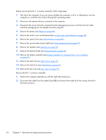
and remove the tape and cable from the routing, Disconnect the cable from the system board
 |
View all HP ProBook 4525s manuals
Add to My Manuals
Save this manual to your list of manuals |
Page 102 highlights
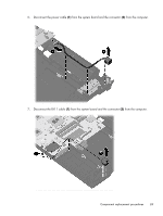
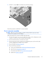
e. Thermal shield (see Thermal shield on page 56) f. Display assembly (see Display assembly on computers with 15.6-in displays on page 71) g. Palm rest (see Palm rest on page 67) h. Hard drive (see Hard drive on page 69) i. Top cover (see Top cover on page 77) Remove the power connector assembly: 1. Position the computer right-side up with the right side toward you. 2. Disconnect the cable from the system board (1) and remove the tape and cable from the routing channel in the base enclosure. 3. Lift the power connector (2) from the base enclosure. Reverse this procedure to install the power connector. 94 Chapter 4 Removal and replacement procedures
-
 1
1 -
2
-
3
-
4
-
5
-
6
-
7
-
8
-
9
-
10
-
11
-
12
-
13
-
14
-
15
-
16
-
17
-
18
-
19
-
20
-
21
-
22
-
23
-
24
-
25
-
26
-
27
-
28
-
29
-
30
-
31
-
32
-
33
-
34
-
35
-
36
-
37
-
38
-
39
-
40
-
41
-
42
-
43
-
44
-
45
-
46
-
47
-
48
-
49
-
50
-
51
-
52
-
53
-
54
-
55
-
56
-
57
-
58
-
59
-
60
-
61
-
62
-
63
-
64
-
65
-
66
-
67
-
68
-
69
-
70
-
71
-
72
-
73
-
74
-
75
-
76
-
77
-
78
-
79
-
80
-
81
-
82
-
83
-
84
-
85
-
86
-
87
-
88
-
89
-
90
-
91
-
92
-
93
-
94
-
95
-
96
-
 97
97 -
 98
98 -
 99
99 -
 100
100 -
 101
101 -
 102
102 -
 103
103 -
 104
104 -
 105
105 -
 106
106 -
 107
107 -
108
-
109
-
110
-
111
-
112
-
113
-
114
-
115
-
116
-
117
-
118
-
119
-
120
-
121
-
122
-
123
-
124
-
125
-
126
-
127
-
128
-
129
-
130
-
131
-
132
-
133
-
134
-
135
-
136
-
137
-
138
-
139
-
140
-
141
-
142
-
143
-
144
-
145
-
146
-
147
-
148
-
149
 |
 |

e.
Thermal shield (see
Thermal shield
on page
56
)
f.
Display assembly (see
Display assembly on computers with 15.6-in displays
on page
71
)
g.
Palm rest (see
Palm rest
on page
67
)
h.
Hard drive (see
Hard drive
on page
69
)
i.
Top cover (see
Top cover
on page
77
)
Remove the power connector assembly:
1.
Position the computer right-side up with the right side toward you.
2.
Disconnect the cable from the system board
(1)
and remove the tape and cable from the routing
channel in the base enclosure.
3.
Lift the power connector
(2)
from the base enclosure.
Reverse this procedure to install the power connector.
94
Chapter 4
Removal and replacement procedures