HP ProBook 4525s HP ProBook 4525s Notebook PC - Maintenance and Service Guide - Page 95
System board
 |
View all HP ProBook 4525s manuals
Add to My Manuals
Save this manual to your list of manuals |
Page 95 highlights
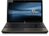
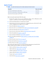
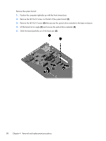
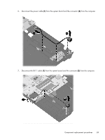
System board NOTE: The system board spare part kit includes replacement thermal material. Description System board with UMA graphics and RTC battery System board with UMA graphics, WWAN capability, and RTC battery System board with discrete graphics and RTC battery Spare part number 613211-001 613212-001 613212-001 Before removing the system board, follow these steps: 1. Shut down the computer. If you are unsure whether the computer is off or in Hibernation, turn the computer on, and then shut it down through the operating system. 2. Disconnect all external devices connected to the computer. 3. Disconnect the power from the computer by first unplugging the power cord from the AC outlet and then unplugging the AC adapter from the computer. 4. Remove the battery (see Battery on page 45). 5. Remove the switch cover and keyboard (see Switch cover and keyboard on page 46). 6. Remove the optical drive (see Optical drive on page 51). 7. Remove the power button board cable (see Power button board on page 53). 8. Remove the speakers (see Speakers on page 55). 9. Remove the thermal shield (see Thermal shield on page 56). 10. Remove the display assembly (see Display assembly on computers with 15.6-in displays on page 71). 11. Remove the palm rest (see Palm rest on page 67). 12. Remove the hard drive (see Hard drive on page 69). 13. Remove the top cover (see Top cover on page 77). When replacing the system board, be sure that the following components are removed from the defective system board and installed on the replacement system board: ● Memory module (see Memory module on page 50) ● WLAN module (see WLAN module on page 58) ● WWAN module (see WWAN module on page 59) ● Modem module (see Modem module on page 83) ● Processor (see Processor on page 65) ● Audio board (see Audio board on page 85) Component replacement procedures 87
-
 1
1 -
2
-
3
-
4
-
5
-
6
-
7
-
8
-
9
-
10
-
11
-
12
-
13
-
14
-
15
-
16
-
17
-
18
-
19
-
20
-
21
-
22
-
23
-
24
-
25
-
26
-
27
-
28
-
29
-
30
-
31
-
32
-
33
-
34
-
35
-
36
-
37
-
38
-
39
-
40
-
41
-
42
-
43
-
44
-
45
-
46
-
47
-
48
-
49
-
50
-
51
-
52
-
53
-
54
-
55
-
56
-
57
-
58
-
59
-
60
-
61
-
62
-
63
-
64
-
65
-
66
-
67
-
68
-
69
-
70
-
71
-
72
-
73
-
74
-
75
-
76
-
77
-
78
-
79
-
80
-
81
-
82
-
83
-
84
-
85
-
86
-
87
-
88
-
89
-
 90
90 -
 91
91 -
 92
92 -
 93
93 -
 94
94 -
 95
95 -
 96
96 -
 97
97 -
 98
98 -
 99
99 -
 100
100 -
101
-
102
-
103
-
104
-
105
-
106
-
107
-
108
-
109
-
110
-
111
-
112
-
113
-
114
-
115
-
116
-
117
-
118
-
119
-
120
-
121
-
122
-
123
-
124
-
125
-
126
-
127
-
128
-
129
-
130
-
131
-
132
-
133
-
134
-
135
-
136
-
137
-
138
-
139
-
140
-
141
-
142
-
143
-
144
-
145
-
146
-
147
-
148
-
149
 |
 |
