HP ProBook 4525s HP ProBook 4525s Notebook PC - Maintenance and Service Guide - Page 55
Two PM2.5×2.5 screws, and then remove it from the computer
 |
View all HP ProBook 4525s manuals
Add to My Manuals
Save this manual to your list of manuals |
Page 55 highlights
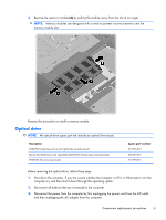
2. To remove the switch cover, remove the following: (1) Two mylar screw covers on the rear edge of the computer (2) Two PM2.5×2.5 screws (3) Three PM2.0×2.5 broadhead screws located in the battery bay 3. Open the computer as far as possible. 4. Slide the switch cover back (1), and then remove it from the computer (2). Component replacement procedures 47
-
 1
1 -
2
-
3
-
4
-
5
-
6
-
7
-
8
-
9
-
10
-
11
-
12
-
13
-
14
-
15
-
16
-
17
-
18
-
19
-
20
-
21
-
22
-
23
-
24
-
25
-
26
-
27
-
28
-
29
-
30
-
31
-
32
-
33
-
34
-
35
-
36
-
37
-
38
-
39
-
40
-
41
-
42
-
43
-
44
-
45
-
46
-
47
-
48
-
49
-
 50
50 -
 51
51 -
 52
52 -
 53
53 -
 54
54 -
 55
55 -
 56
56 -
 57
57 -
 58
58 -
 59
59 -
 60
60 -
61
-
62
-
63
-
64
-
65
-
66
-
67
-
68
-
69
-
70
-
71
-
72
-
73
-
74
-
75
-
76
-
77
-
78
-
79
-
80
-
81
-
82
-
83
-
84
-
85
-
86
-
87
-
88
-
89
-
90
-
91
-
92
-
93
-
94
-
95
-
96
-
97
-
98
-
99
-
100
-
101
-
102
-
103
-
104
-
105
-
106
-
107
-
108
-
109
-
110
-
111
-
112
-
113
-
114
-
115
-
116
-
117
-
118
-
119
-
120
-
121
-
122
-
123
-
124
-
125
-
126
-
127
-
128
-
129
-
130
-
131
-
132
-
133
-
134
-
135
-
136
-
137
-
138
-
139
-
140
-
141
-
142
-
143
-
144
-
145
-
146
-
147
-
148
-
149
 |
 |

2.
To remove the switch cover, remove the following:
(1)
Two mylar screw covers on the rear edge of the computer
(2)
Two PM2.5×2.5 screws
(3)
Three PM2.0×2.5 broadhead screws located in the battery bay
3.
Open the computer as far as possible.
4.
Slide the switch cover back
(1)
, and then remove it from the computer
(2)
.
Component replacement procedures
47