HP ProBook 4525s HP ProBook 4525s Notebook PC - Maintenance and Service Guide - Page 84
Peel the WLAN, Route the antenna cables
 |
View all HP ProBook 4525s manuals
Add to My Manuals
Save this manual to your list of manuals |
Page 84 highlights
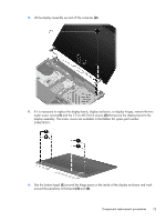
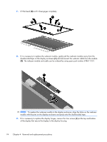
2. Remove the webcam cable (3) from the raceway and then, remove the cable assembly (4). NOTE: The cables are attached to the display panel with adhesive tape. To remove the WLAN and WWAN antennas: 1. Peel the WLAN (1) and WWAN (2) antenna receivers from the housing. 2. Route the antenna cables (3) out of the routing channels in the inside of the display housing. Reverse this procedure to install the display assembly. 76 Chapter 4 Removal and replacement procedures
-
 1
1 -
2
-
3
-
4
-
5
-
6
-
7
-
8
-
9
-
10
-
11
-
12
-
13
-
14
-
15
-
16
-
17
-
18
-
19
-
20
-
21
-
22
-
23
-
24
-
25
-
26
-
27
-
28
-
29
-
30
-
31
-
32
-
33
-
34
-
35
-
36
-
37
-
38
-
39
-
40
-
41
-
42
-
43
-
44
-
45
-
46
-
47
-
48
-
49
-
50
-
51
-
52
-
53
-
54
-
55
-
56
-
57
-
58
-
59
-
60
-
61
-
62
-
63
-
64
-
65
-
66
-
67
-
68
-
69
-
70
-
71
-
72
-
73
-
74
-
75
-
76
-
77
-
78
-
 79
79 -
 80
80 -
 81
81 -
 82
82 -
 83
83 -
 84
84 -
 85
85 -
 86
86 -
 87
87 -
 88
88 -
 89
89 -
90
-
91
-
92
-
93
-
94
-
95
-
96
-
97
-
98
-
99
-
100
-
101
-
102
-
103
-
104
-
105
-
106
-
107
-
108
-
109
-
110
-
111
-
112
-
113
-
114
-
115
-
116
-
117
-
118
-
119
-
120
-
121
-
122
-
123
-
124
-
125
-
126
-
127
-
128
-
129
-
130
-
131
-
132
-
133
-
134
-
135
-
136
-
137
-
138
-
139
-
140
-
141
-
142
-
143
-
144
-
145
-
146
-
147
-
148
-
149
 |
 |

2.
Remove the webcam cable
(3)
from the raceway and then, remove the cable assembly
(4)
.
NOTE:
The cables are attached to the display panel with adhesive tape.
To remove the WLAN and WWAN antennas:
1.
Peel the WLAN
(1)
and WWAN
(2)
antenna receivers from the housing.
2.
Route the antenna cables
(3)
out of the routing channels in the inside of the display housing.
Reverse this procedure to install the display assembly.
76
Chapter 4
Removal and replacement procedures