HP ProBook 4525s HP ProBook 4525s Notebook PC - Maintenance and Service Guide - Page 70
Position the computer right-side up with the front toward you.
 |
View all HP ProBook 4525s manuals
Add to My Manuals
Save this manual to your list of manuals |
Page 70 highlights
4. Remove the battery (see Battery on page 45). 5. Remove the following components: a. Switch cover and keyboard (see Switch cover and keyboard on page 46). NOTE: It is not necessary to disconnect the keyboard to remove or install the heat sink. b. Thermal shield (see Thermal shield on page 56). Remove the heat sink: ● For computers with discrete subsystem memory on the system board, follow these steps: 1. Position the computer right-side up with the front toward you. 2. Following the sequence stamped into the heat sink, loosen the six captive screws (1), (2), (3), (4), (5), (6), around the processor. 3. Disconnect the fan cable from the system board (7), and then remove the heat sink (8). 62 Chapter 4 Removal and replacement procedures
-
 1
1 -
2
-
3
-
4
-
5
-
6
-
7
-
8
-
9
-
10
-
11
-
12
-
13
-
14
-
15
-
16
-
17
-
18
-
19
-
20
-
21
-
22
-
23
-
24
-
25
-
26
-
27
-
28
-
29
-
30
-
31
-
32
-
33
-
34
-
35
-
36
-
37
-
38
-
39
-
40
-
41
-
42
-
43
-
44
-
45
-
46
-
47
-
48
-
49
-
50
-
51
-
52
-
53
-
54
-
55
-
56
-
57
-
58
-
59
-
60
-
61
-
62
-
63
-
64
-
 65
65 -
 66
66 -
 67
67 -
 68
68 -
 69
69 -
 70
70 -
 71
71 -
 72
72 -
 73
73 -
 74
74 -
 75
75 -
76
-
77
-
78
-
79
-
80
-
81
-
82
-
83
-
84
-
85
-
86
-
87
-
88
-
89
-
90
-
91
-
92
-
93
-
94
-
95
-
96
-
97
-
98
-
99
-
100
-
101
-
102
-
103
-
104
-
105
-
106
-
107
-
108
-
109
-
110
-
111
-
112
-
113
-
114
-
115
-
116
-
117
-
118
-
119
-
120
-
121
-
122
-
123
-
124
-
125
-
126
-
127
-
128
-
129
-
130
-
131
-
132
-
133
-
134
-
135
-
136
-
137
-
138
-
139
-
140
-
141
-
142
-
143
-
144
-
145
-
146
-
147
-
148
-
149
 |
 |

4.
Remove the battery (see
Battery
on page
45
).
5.
Remove the following components:
a.
Switch cover and keyboard (see
Switch cover and keyboard
on page
46
).
NOTE:
It is not necessary to disconnect the keyboard to remove or install the heat sink.
b.
Thermal shield (see
Thermal shield
on page
56
).
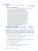
Remove the heat sink:
●
For computers with discrete subsystem memory on the system board, follow these steps:
1.
Position the computer right-side up with the front toward you.
2.
Following the sequence stamped into the heat sink, loosen the six captive screws
(1)
,
(2)
,
(3)
,
(4)
,
(5)
,
(6)
, around the processor.
3.
Disconnect the fan cable from the system board
(7)
, and then remove the heat sink
(8)
.
62
Chapter 4
Removal and replacement procedures