HP ProBook 4525s HP ProBook 4525s Notebook PC - Maintenance and Service Guide - Page 80
CAUTION, Open the computer as far as possible.
 |
View all HP ProBook 4525s manuals
Add to My Manuals
Save this manual to your list of manuals |
Page 80 highlights
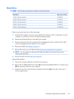
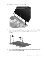
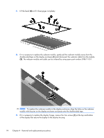
7. Remove the speakers (see Speakers on page 55) 8. Remove the thermal shield (see Thermal shield on page 56). Remove the display cables: 1. Remove the tape that holds the cables in place (1). Disconnect the display and webcam cables from the system board and from the routing channels. 2. Disconnect the cable connectors for the display (2) and microphone (3) from the system board. 3. Disconnect the WLAN and WWAN cables (4) from the tape and from the routing channels built into the top cover. Remove the display assembly: 1. Position the computer right-side up with the front toward you. 2. Open the computer as far as possible. CAUTION: Support the display assembly when removing the retaining screws. Failure to support the display assembly can result in damage to the display assembly and other computer components. 3. Remove the six Torx M2.5×6.0 screws (1) that secure the display assembly to the computer. 72 Chapter 4 Removal and replacement procedures
-
 1
1 -
2
-
3
-
4
-
5
-
6
-
7
-
8
-
9
-
10
-
11
-
12
-
13
-
14
-
15
-
16
-
17
-
18
-
19
-
20
-
21
-
22
-
23
-
24
-
25
-
26
-
27
-
28
-
29
-
30
-
31
-
32
-
33
-
34
-
35
-
36
-
37
-
38
-
39
-
40
-
41
-
42
-
43
-
44
-
45
-
46
-
47
-
48
-
49
-
50
-
51
-
52
-
53
-
54
-
55
-
56
-
57
-
58
-
59
-
60
-
61
-
62
-
63
-
64
-
65
-
66
-
67
-
68
-
69
-
70
-
71
-
72
-
73
-
74
-
 75
75 -
 76
76 -
 77
77 -
 78
78 -
 79
79 -
 80
80 -
 81
81 -
 82
82 -
 83
83 -
 84
84 -
 85
85 -
86
-
87
-
88
-
89
-
90
-
91
-
92
-
93
-
94
-
95
-
96
-
97
-
98
-
99
-
100
-
101
-
102
-
103
-
104
-
105
-
106
-
107
-
108
-
109
-
110
-
111
-
112
-
113
-
114
-
115
-
116
-
117
-
118
-
119
-
120
-
121
-
122
-
123
-
124
-
125
-
126
-
127
-
128
-
129
-
130
-
131
-
132
-
133
-
134
-
135
-
136
-
137
-
138
-
139
-
140
-
141
-
142
-
143
-
144
-
145
-
146
-
147
-
148
-
149
 |
 |
