HP StorageWorks 4/32 HP StorageWorks DC and DC04 SAN Backbone Director Switche - Page 104
Installing components into the new chassis, Configuring the new chassis serial number
 |
View all HP StorageWorks 4/32 manuals
Add to My Manuals
Save this manual to your list of manuals |
Page 104 highlights
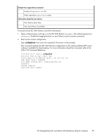
5. Use a lift to raise the chassis to the correct level. If installing the chassis in a cabinet, follow the instructions provided by the rack kit manufacturer. Installing components into the new chassis Install the field replaceable units (FRUs) in the chassis. CAUTION: Wear a grounded ESD strap when handling DC SAN Director components and port blades. The chassis provides a grounding connection above the power connectors. Also, store ESD-sensitive components in antistatic packaging. 1. Replace the WWN bezel (logo plate) and WWN cards (see "Installing the WWN bezel (logo plate) and WWN card" on page 95). 2. Replace the blower assemblies (see "Installing a blower assembly" on page 90). 3. Replace the power supplies or filler panels (see "Installing a power supply" on page 88). 4. Replace the control processor blades (CP8) (see "Installing a control processor blade (CP8)" on page 83). 5. Replace the core switch blades (CR8) (see "Installing a core switch blade (CR8)" on page 87). 6. Replace the port blades or filler panels (see "Installing a Director blade" on page 77). 7. Replace the cable management comb (see "Installing a cable management comb" on page 75). 8. Connect the power cords to the power supplies and the power outlets. 9. Power-on the DC SAN Director. 10. The DC SAN Director performs a power-on self-test (POST). The POST takes a minimum of three minutes and is complete when LED activity returns to standard state. 11. Verify that the DC SAN Director is powered on and POST is complete (all power LED indicators on the port, control processor, and core switch blades should be a steady green). 12. Verify that all components are functioning correctly by checking their LEDs. If the LEDs do not indicate correct operation, try reinstalling the corresponding component. Configuring the new chassis serial number To configure a new chassis serial number: 104 Replacing DC SAN Director field-replaceable units (FRUs)
-
 1
1 -
2
-
3
-
4
-
5
-
6
-
7
-
8
-
9
-
10
-
11
-
12
-
13
-
14
-
15
-
16
-
17
-
18
-
19
-
20
-
21
-
22
-
23
-
24
-
25
-
26
-
27
-
28
-
29
-
30
-
31
-
32
-
33
-
34
-
35
-
36
-
37
-
38
-
39
-
40
-
41
-
42
-
43
-
44
-
45
-
46
-
47
-
48
-
49
-
50
-
51
-
52
-
53
-
54
-
55
-
56
-
57
-
58
-
59
-
60
-
61
-
62
-
63
-
64
-
65
-
66
-
67
-
68
-
69
-
70
-
71
-
72
-
73
-
74
-
75
-
76
-
77
-
78
-
79
-
80
-
81
-
82
-
83
-
84
-
85
-
86
-
87
-
88
-
89
-
90
-
91
-
92
-
93
-
94
-
95
-
96
-
97
-
98
-
 99
99 -
 100
100 -
 101
101 -
 102
102 -
 103
103 -
 104
104 -
 105
105 -
 106
106 -
 107
107 -
 108
108 -
 109
109 -
110
-
111
-
112
-
113
-
114
-
115
-
116
-
117
-
118
-
119
-
120
-
121
-
122
-
123
-
124
-
125
-
126
-
127
-
128
-
129
-
130
-
131
-
132
-
133
-
134
-
135
-
136
-
137
-
138
-
139
-
140
-
141
-
142
-
143
-
144
-
145
-
146
-
147
-
148
-
149
-
150
-
151
-
152
-
153
-
154
-
155
-
156
-
157
-
158
-
159
-
160
-
161
-
162
-
163
-
164
-
165
-
166
-
167
-
168
-
169
-
170
-
171
-
172
-
173
-
174
-
175
-
176
-
177
-
178
-
179
-
180
-
181
-
182
-
183
-
184
-
185
-
186
-
187
-
188
-
189
-
190
-
191
-
192
-
193
-
194
-
195
-
196
-
197
-
198
-
199
-
200
-
201
-
202
-
203
-
204
-
205
-
206
-
207
-
208
-
209
-
210
-
211
-
212
-
213
-
214
-
215
-
216
-
217
-
218
-
219
-
220
-
221
-
222
-
223
-
224
-
225
-
226
-
227
-
228
-
229
-
230
-
231
-
232
-
233
-
234
-
235
-
236
-
237
-
238
-
239
-
240
-
241
-
242
-
243
-
244
-
245
-
246
-
247
-
248
-
249
-
250
-
251
-
252
-
253
-
254
-
255
-
256
 |
 |
