HP StorageWorks 4/32 HP StorageWorks DC and DC04 SAN Backbone Director Switche - Page 136
Installing the DC04 SAN Director shipping brackets, Table 29
 |
View all HP StorageWorks 4/32 manuals
Add to My Manuals
Save this manual to your list of manuals |
Page 136 highlights
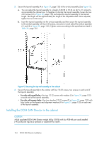
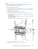
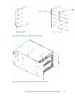
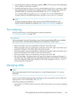
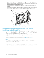
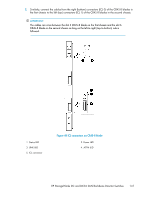
7. Install the cable management finger assembly. See Installing a cable management finger assembly, page 171. Installing the DC04 SAN Director shipping brackets This section describes how to install the DC04 SAN Director shipping brackets. (See Figure 45). These brackets are required when the DC04 SAN Director is shipped installed in a cabinet. 1. Before installing the DC04 SAN Director in the cabinet, remove the 10 flathead 6-32 screws located on both the left and right side chassis panels. See Figure 46. 2. Install both side plates using the ten 6-32 panhead screws supplied with the kit. NOTE: The left and right side plates are different. The left side and right side plates are marked with "A" and "B" respectively. See Figure 46. NOTE: The side plates have five sets of discrete holes, marked 27 through 31. Use the holes that correspond with the cabinet's rail-to-rail depth. See Table 29. Tighten the screws to 10 in/lbs. 3. Install the DC04 SAN Director in the cabinet. 4. Install the clip nuts or nut retainers. The clip nuts are used with cabinets that have square holes, and nut retainers are used with cabinets that have round holes. The locations of the clip nuts or nut retainers match the location for the port-side rack brackets. 5. Secure the L-brackets to the cabinet rails using the six 10-32 panhead screws with square cone washers supplied with the kit. Tighten the screws to 32 in/lbs. NOTE: The left and right side brackets are different. The left side and right side L-brackets are marked with A and B respectively. See Figure 47. 6. After mounting the L-brackets to the rails, secure them to the side plates using the 18 10-32 panhead screws with square cone washers supplied with the kit. See Figure 47. Tighten the screws to 32 in/lbs. Table 29 Cabinet rail-to-rail depths Column ID 27 Rail-to-rail depth (inches) 27-27.5 28 27.5-28.5 29 28.5-29.5 30 29.5-30.5 31 30.5-31 136 DC04 SAN Director Installation
-
 1
1 -
2
-
3
-
4
-
5
-
6
-
7
-
8
-
9
-
10
-
11
-
12
-
13
-
14
-
15
-
16
-
17
-
18
-
19
-
20
-
21
-
22
-
23
-
24
-
25
-
26
-
27
-
28
-
29
-
30
-
31
-
32
-
33
-
34
-
35
-
36
-
37
-
38
-
39
-
40
-
41
-
42
-
43
-
44
-
45
-
46
-
47
-
48
-
49
-
50
-
51
-
52
-
53
-
54
-
55
-
56
-
57
-
58
-
59
-
60
-
61
-
62
-
63
-
64
-
65
-
66
-
67
-
68
-
69
-
70
-
71
-
72
-
73
-
74
-
75
-
76
-
77
-
78
-
79
-
80
-
81
-
82
-
83
-
84
-
85
-
86
-
87
-
88
-
89
-
90
-
91
-
92
-
93
-
94
-
95
-
96
-
97
-
98
-
99
-
100
-
101
-
102
-
103
-
104
-
105
-
106
-
107
-
108
-
109
-
110
-
111
-
112
-
113
-
114
-
115
-
116
-
117
-
118
-
119
-
120
-
121
-
122
-
123
-
124
-
125
-
126
-
127
-
128
-
129
-
130
-
 131
131 -
 132
132 -
 133
133 -
 134
134 -
 135
135 -
 136
136 -
 137
137 -
 138
138 -
 139
139 -
 140
140 -
 141
141 -
142
-
143
-
144
-
145
-
146
-
147
-
148
-
149
-
150
-
151
-
152
-
153
-
154
-
155
-
156
-
157
-
158
-
159
-
160
-
161
-
162
-
163
-
164
-
165
-
166
-
167
-
168
-
169
-
170
-
171
-
172
-
173
-
174
-
175
-
176
-
177
-
178
-
179
-
180
-
181
-
182
-
183
-
184
-
185
-
186
-
187
-
188
-
189
-
190
-
191
-
192
-
193
-
194
-
195
-
196
-
197
-
198
-
199
-
200
-
201
-
202
-
203
-
204
-
205
-
206
-
207
-
208
-
209
-
210
-
211
-
212
-
213
-
214
-
215
-
216
-
217
-
218
-
219
-
220
-
221
-
222
-
223
-
224
-
225
-
226
-
227
-
228
-
229
-
230
-
231
-
232
-
233
-
234
-
235
-
236
-
237
-
238
-
239
-
240
-
241
-
242
-
243
-
244
-
245
-
246
-
247
-
248
-
249
-
250
-
251
-
252
-
253
-
254
-
255
-
256
 |
 |
