HP StorageWorks 4/32 HP StorageWorks DC and DC04 SAN Backbone Director Switche - Page 31
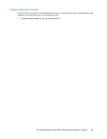
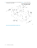
on Remove the cable management comb. See
 |
View all HP StorageWorks 4/32 manuals
Add to My Manuals
Save this manual to your list of manuals |
Page 31 highlights
4. Ensure that dedicated electrical branch circuits with the following characteristics are available: • 200-240 VAC, 50-60 Hz (two branch circuits) • 110-120 VAC, 50-60 Hz (up to four branch circuits) • One power cable per power supply is required • Protected by a circuit breaker in accordance with local electrical codes • Supply circuit, line fusing, and wire size adequate to the electrical rating on the chassis nameplate • Location close to the chassis and easily accessible • Grounded outlets installed by a licensed electrician, compatible with the power cords TIP: To maximize fault tolerance, connect each power cord to a separate power source. 5. Ensure that the air intake and exhaust vents have a minimum of 2 in. of airspace. 6. Ensure that the air temperature on the air intake side is less than 40˚ Celsius (104˚ Fahrenheit) during operation. CAUTION: A fully populated DC SAN Director (eight FC8-48 port cards, 384 ports) weighs approximately 104 kg (228 lbs) and requires a hydraulic or assisted lift to install it. 7. Remove the upper portion of the packing crate while the DC SAN Director is still in the shipping area, to reduce clutter at the installation site: a. Remove the straps securing the carton to the pallet. b. Lift the top of the crate off the pallet. Leave the foam on top of the chassis to hold the kits in place during transportation to the installation area. Save the shipping crate and related items for any future shipping requirements. 8. Transport the chassis on the pallet to the installation area, using a pallet jack or other assisted lift. The plastic pallet cannot fit through doorways that are less than 91 cm (36 in.) wide. 9. Remove the 14U rack mount kit, accessory kit, packing foam, and anti-static plastic from the chassis and set aside. 10. Remove the chassis door from the DC SAN Director. See "Removing the chassis door" on page 38. 11. Remove the cable management comb. See "Removing a cable management comb" on page 74. 12. Position the pallet so that the bottom of the chassis is level with the installation surface. 13. If the chassis is on a pallet jack or lift, stabilize the pallet jack or lift to prevent it from moving during the transfer. 14. Unscrew the four bolts holding the DC SAN Director to the pallet and remove the brackets. 15. Gently slide the chassis onto the final installation surface, ensuring that it remains supported during the transfer. 16. Ensure that the chassis is oriented so that the non-port side has access to intake air (cool). 17. Reinstall the cable management comb. See "Installing a cable management comb" on page 75. 18. Reinstall the chassis door. See "Installing the chassis door" on page 74. HP StorageWorks DC and DC04 SAN Backbone Director Switches 31
-
 1
1 -
2
-
3
-
4
-
5
-
6
-
7
-
8
-
9
-
10
-
11
-
12
-
13
-
14
-
15
-
16
-
17
-
18
-
19
-
20
-
21
-
22
-
23
-
24
-
25
-
 26
26 -
 27
27 -
 28
28 -
 29
29 -
 30
30 -
 31
31 -
 32
32 -
 33
33 -
 34
34 -
 35
35 -
 36
36 -
37
-
38
-
39
-
40
-
41
-
42
-
43
-
44
-
45
-
46
-
47
-
48
-
49
-
50
-
51
-
52
-
53
-
54
-
55
-
56
-
57
-
58
-
59
-
60
-
61
-
62
-
63
-
64
-
65
-
66
-
67
-
68
-
69
-
70
-
71
-
72
-
73
-
74
-
75
-
76
-
77
-
78
-
79
-
80
-
81
-
82
-
83
-
84
-
85
-
86
-
87
-
88
-
89
-
90
-
91
-
92
-
93
-
94
-
95
-
96
-
97
-
98
-
99
-
100
-
101
-
102
-
103
-
104
-
105
-
106
-
107
-
108
-
109
-
110
-
111
-
112
-
113
-
114
-
115
-
116
-
117
-
118
-
119
-
120
-
121
-
122
-
123
-
124
-
125
-
126
-
127
-
128
-
129
-
130
-
131
-
132
-
133
-
134
-
135
-
136
-
137
-
138
-
139
-
140
-
141
-
142
-
143
-
144
-
145
-
146
-
147
-
148
-
149
-
150
-
151
-
152
-
153
-
154
-
155
-
156
-
157
-
158
-
159
-
160
-
161
-
162
-
163
-
164
-
165
-
166
-
167
-
168
-
169
-
170
-
171
-
172
-
173
-
174
-
175
-
176
-
177
-
178
-
179
-
180
-
181
-
182
-
183
-
184
-
185
-
186
-
187
-
188
-
189
-
190
-
191
-
192
-
193
-
194
-
195
-
196
-
197
-
198
-
199
-
200
-
201
-
202
-
203
-
204
-
205
-
206
-
207
-
208
-
209
-
210
-
211
-
212
-
213
-
214
-
215
-
216
-
217
-
218
-
219
-
220
-
221
-
222
-
223
-
224
-
225
-
226
-
227
-
228
-
229
-
230
-
231
-
232
-
233
-
234
-
235
-
236
-
237
-
238
-
239
-
240
-
241
-
242
-
243
-
244
-
245
-
246
-
247
-
248
-
249
-
250
-
251
-
252
-
253
-
254
-
255
-
256
 |
 |
