HP Tc2100 hp server tc2100 installation sheet (English)
HP Tc2100 - Server - 128 MB RAM Manual
 |
View all HP Tc2100 manuals
Add to My Manuals
Save this manual to your list of manuals |
HP Tc2100 manual content summary:
- HP Tc2100 | hp server tc2100 installation sheet (English) - Page 1
HP Server tc2100 Installation Guide HP Part Number P4648-90000 Printed in August 2001 - HP Tc2100 | hp server tc2100 installation sheet (English) - Page 2
the use or reliability of its software on equipment that is not furnished . All rights are reserved. No part of this document may be photocopied, guide is for the person who installs, administers, and troubleshoots LAN servers. Hewlett-Packard Company assumes you are qualified in the servicing - HP Tc2100 | hp server tc2100 installation sheet (English) - Page 3
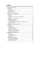
and Indicators 8 Rear View ...10 Applying Power to the HP Server 11 Powering-Up the Server 12 Powering-Down the Server 13 Connecting AC Power to Multiple-Server Configurations 13 Sleep States (ACPI 13 3 Opening and Closing the HP Server 17 Introduction ...17 Tools Required 17 Removing - HP Tc2100 | hp server tc2100 installation sheet (English) - Page 4
Drive 34 5 Installing Additional Memory 37 Introduction ...37 Tools Required 37 Memory Installation Guidelines 37 Installing Additional Power Supply 56 8 Configuring the HP Server 57 Introduction ...57 HP Startup CD-ROM 58 Accessing the HP Startup CD-ROM 58 Contents of the HP Startup - HP Tc2100 | hp server tc2100 installation sheet (English) - Page 5
Troubleshooting 69 Introduction ...69 Tools Required 70 Common Installation Problems 70 Troubleshooting Sequence 71 Server Will Not Power On 71 Problems after Server is Powered Problems Running the Setup Utility 82 A Specifications Service and Support 93 D Warranty and Software License 95 v - HP Tc2100 | hp server tc2100 installation sheet (English) - Page 6
Contents Warranty ...95 HP Software Product License Agreement 95 Non-Nuclear Usage 96 Index...97 vi - HP Tc2100 | hp server tc2100 installation sheet (English) - Page 7
. HP Server tc2100 Installation Kit This kit contains the ReadFirst sheet, the Installation Guides, and the HP Startup CD-ROM shipped with each HP Server tc2100. HP Server tc2100 Installation Guide This document describes installation, hardware upgrades, configuration, and troubleshooting of your HP - HP Tc2100 | hp server tc2100 installation sheet (English) - Page 8
Chapter 1 Setting Up the HP Server HP Server tc2100 NOS Installation Guide This document describes installation of the various supported NOSs, loading drivers, flashing BIOS, and using HP DiagTools to verify your HP Server's integrity. Installing the HP Server 5) If there are no options to - HP Tc2100 | hp server tc2100 installation sheet (English) - Page 9
on the model. • For details refer to Chapter 4, "Installing Mass Storage Devices." 6c) Add Memory (DIMMs) 6d) Add PCI Accessory Boards • You can install more memory or upgrade the existing memory. Use only HP supported DIMMs. • Supported DIMMs may be installed in any combination, in any slot, but - HP Tc2100 | hp server tc2100 installation sheet (English) - Page 10
refer to Chapter 3, "Opening and Closing the HP Server." Applying Power to the Server 7) Check/Set the Power Supply Input Voltage Power Connector • Check the input voltage switch on the power supply located on the rear of the Server below the power connector, as shown below. • The input voltage - HP Tc2100 | hp server tc2100 installation sheet (English) - Page 11
the BIOS and install the NOS drivers. • If the Windows PC does not auto-start the Startup menu, start it by opening the Startup.htm file, found at the root level of the Startup CD. • Refer to the Welcome menu on the Startup CD-ROM, or the HP Server tc2100 NOS Installation Guide for instructions. 5 - HP Tc2100 | hp server tc2100 installation sheet (English) - Page 12
and read the desired NOS installation topic in the HP Server tc2100 NOS Installation Guide before installing the desired NOS. • The NOS Installation Guide provides the instructions for installing all the supported NOSs. • The NOS drivers are normally installed from the diskettes you create, but - HP Tc2100 | hp server tc2100 installation sheet (English) - Page 13
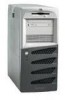
Before operating the HP Tower Server tc2100, familiarize yourself with the HP Server's controls, ports, and indicators, as shown in Figures 2-1 through 2-3. Front Panel The front panel of the HP Server tc2100 provides the controls and indicators commonly used when operating the Server. Power On/Off - HP Tc2100 | hp server tc2100 installation sheet (English) - Page 14
not support power management based on the ACPI (Advanced Configuration and Power Management Interface) standard. Refer to "Applying Power to the HP Server" and which give control and operational status of the respective device. The specific controls and indicators depend on the type and model of the - HP Tc2100 | hp server tc2100 installation sheet (English) - Page 15
Tape Drive (Optional) Figure 2-2. Input and Storage Device Controls and Indicators Table 2-2. HP Backup Tape Drive LED Codes Left LED Off On Flashing* Pulsing** Right LED Off Off Off Off Definition No Power Cartridge loaded, drive ready, but No activity Cartridge is loading/unloading, or in - HP Tc2100 | hp server tc2100 installation sheet (English) - Page 16
related items at the rear of the Server are listed below and shown in Figure 2-3. • The power connector accepts a standard power cable to connect the HP Server tc2100 with the site power source. • The input voltage selector switch is used to adapt the power supply to the input line voltage. The two - HP Tc2100 | hp server tc2100 installation sheet (English) - Page 17
2 Keylock LAN System Fan External SCSI (SCSI Model only) Figure 2-3. Rear Panel and Ports Applying Power to the HP Server If you chose to use sleep states in conjunction with the HP Server tc2100, refer to "Sleep States (ACPI)" later in this section and your respective NOS before attempting to - HP Tc2100 | hp server tc2100 installation sheet (English) - Page 18
bezel. See Figure 2-1. When you press the power button on the front bezel, the Server powers up and loads the operating system. The system runs a set of Power On Self Tests (POST) during this process. For details refer to Chapter 8, "Configuring the HP Server" and Chapter 9, "Troubleshooting." 12 - HP Tc2100 | hp server tc2100 installation sheet (English) - Page 19
any kind of hardware or software upgrade, ensure the Server's data has been backed up. o Follow instructions in your network operating system (NOS) documentation to gracefully shut down all networking software and applications. WARNING The power supply will continue to provide standby current - HP Tc2100 | hp server tc2100 installation sheet (English) - Page 20
and the user options are specific to the particular ACPI-compliant NOS installed on the Server. If your NOS is ACPI-compliant, refer to the (BIOS) Setup Utility and the power management features provided in the NOS instructions for more information. The HP Server's power button can be configured to - HP Tc2100 | hp server tc2100 installation sheet (English) - Page 21
Controls, Ports, and Indicators CAUTION If the power button override is used, there is a strong possibility of corrupted or lost data. Refer to the BIOS Setup Utility in Chapter 8, "Configuring the HP Server" and your NOS documentation for instructions on setting up Sleep States and transitioning - HP Tc2100 | hp server tc2100 installation sheet (English) - Page 22
- HP Tc2100 | hp server tc2100 installation sheet (English) - Page 23
and replace the HP Tower Server tc2100's left side cover and the upper front bezel. WARNING Before removing the cover, always disconnect the power cord and unplug telephone cables. Disconnect the power cord to avoid exposure to high energy levels that may cause burns when parts are short-circuited - HP Tc2100 | hp server tc2100 installation sheet (English) - Page 24
Chapter 3 Opening and Closing the HP Server Removing the Side Cover 1. Turn off the Server and disconnect the power cord. Refer to Chapter 2, "Controls, Ports, and Indicators" for shutdown procedure. 2. If phone lines are connected to the Server, remove the phone lines. 3. Insert the key into the - HP Tc2100 | hp server tc2100 installation sheet (English) - Page 25
Chapter 3 Opening and Closing the HP Server Figure 3-2. Removing the Left Side Cover 6. Place the mass storage devices into the upper drive shelves (first four shelves or common trays) of the Server. 1. Once you have removed the left side cover, locate the front bezel release tabs just behind - HP Tc2100 | hp server tc2100 installation sheet (English) - Page 26
Chapter 3 Opening and Closing the HP Server Release Tabs (2) Figure 3-3. Removing Upper Front Bezel 4. Place the upper front bezel in a safe place for re-installation later. Replacing the Upper Front Bezel The - HP Tc2100 | hp server tc2100 installation sheet (English) - Page 27
3 Opening and Closing the HP Server Hinge Teeth (4) Figure 3-4. Replacing the Front Bezel Replacing the Left Side Cover To replace the left side cover, follow these steps: 1. If you have been installing or replacing accessories in the Server, return the Server to its normal upright position - HP Tc2100 | hp server tc2100 installation sheet (English) - Page 28
Chapter 3 Opening and Closing the HP Server Latch Hinge Tabs Figure 3-5. Replacing the Left Side Cover 5. If you want the left side cover locked, turn the key to re-lock the left side cover with the lock at the rear of the Server. See Figure 3-1. 22 - HP Tc2100 | hp server tc2100 installation sheet (English) - Page 29
IDE or SCSI) and the optional tape backup (DAT) drive. The HP Tower Server tc2100 comes standard with one flexible disk drive, one IDE CD-ROM, and device's documentation for additional tool requirements. • Torx T-15 driver • ¼-inch flat blade screwdriver Mass Storage Guidelines • General Guidelines - HP Tc2100 | hp server tc2100 installation sheet (English) - Page 30
Refer to "System Board Layout" in Appendix A, "Specifications." o The IDE CD-ROM uses one connector on high voltage differential (HVD) SCSI devices in the Server or damage to the controller and other devices may on the SCSI drive. o Use only HP Ultra 160 SCSI LVD (1-inch) low profile 3.5-inch hard - HP Tc2100 | hp server tc2100 installation sheet (English) - Page 31
Chapter 4 Installing Mass Storage Devices Boot Priority The HP Server tc2100 is provided in two models, IDE or SCSI, and the model type affects the boot priority. The HP Server searches for bootable devices in a specific order, which is set up in the BIOS Utility. IDE Model Boot Order: 1. Flexible - HP Tc2100 | hp server tc2100 installation sheet (English) - Page 32
of the IDE mass storage devices, if you have selected an IDE version of the HP Server tc2100. IDE Controller Configuration The embedded IDE controller is available for both models (IDE or SCSI) of the HP Server. The embedded IDE controller is an Ultra DMA33/66/100 E-IDE dual channel controller - HP Tc2100 | hp server tc2100 installation sheet (English) - Page 33
SCSI mass storage devices, if you have selected a SCSI version of the HP Server tc2100. The base SCSI model configuration has at least one SCSI hard drive (shelf to the internal SCSI connector. The HP Server tc2100 will support an HP NetRAID 1M controller board, separate from the SCSI controller - HP Tc2100 | hp server tc2100 installation sheet (English) - Page 34
model of the HP Server. Table 4-2. SCSI supported by Hewlett-Packard. ** A 50-to-68-pin SCSI adapter is provided with the HP backup tape drive. *** The single channel SCSI controller can support Server is already installed and operating, power down the Server as described in Chapter 2, "Controls, - HP Tc2100 | hp server tc2100 installation sheet (English) - Page 35
If necessary, label each one to expedite re-assembly. 3. Remove the side cover from the Server as described in Chapter 3, "Opening and Closing the HP Server." 4. Disconnect the data and power cables to the existing hard drive in the drive cage. See Figure 4-1. CAUTION Install and remove connectors - HP Tc2100 | hp server tc2100 installation sheet (English) - Page 36
SCSI ID jumper for address = ID 1. Refer to the documentation provided with the hard drive. 8. Slide the drive into the upper cage opening with the data and power connectors facing out of the drive cage. See Figures 4-2 and 4-3. 30 - HP Tc2100 | hp server tc2100 installation sheet (English) - Page 37
device. Damage caused by incorrect mounting screws is not covered by the HP warranty. 9. Align the drive's screw holes with the holes in the cage slide into the slots provided. See Figures 4-2 and 4-3. 11. Connect the data cable to the hard disk drives, as described below: Refer to Figure 4-1. a. - HP Tc2100 | hp server tc2100 installation sheet (English) - Page 38
, Ports, and Indicators." 2. Disconnect the power cables and any external cables connected to the Server. If necessary, label each one to expedite re-assembly. 3. Remove the left side cover from the Server. Refer to Chapter 3, "Opening and Closing the HP Server." 4. Remove the upper front bezel - HP Tc2100 | hp server tc2100 installation sheet (English) - Page 39
¼-inch in length. Longer screws may cause internal damage to the mass storage device. Damage caused by incorrect mounting screws is not covered by the HP warranty. 7. Install the hard disk drive, as described below: a. Place the hard disk drive into the tray and use the screws provided to secure it - HP Tc2100 | hp server tc2100 installation sheet (English) - Page 40
Installing Mass Storage Devices 8. Connect the data cable to the hard disk drive, power cables and any external cables connected to the Server. If necessary, label each one to expedite re-assembly. 3. Remove the left side cover from the Server. Refer to Chapter 3, "Opening and Closing the HP Server - HP Tc2100 | hp server tc2100 installation sheet (English) - Page 41
for address = ID 3 on the tape drive. The HP SureStore DAT 24i backup tape drive is shipped with the on the tape drive. If not, follow the instructions provided with the tape drive to connect the SCSI data and power cables to the rear of the back up tape drive. The SCSI data and power cables for - HP Tc2100 | hp server tc2100 installation sheet (English) - Page 42
Installing Mass Storage Devices 10. Replace the upper bezel and the left side cover. 12. Replace the external cables, power cord, and then restore power to the Server. The SCSISelect Utility automatically detects the new SCSI backup tape drive, but you should check the SCSISelect settings and make - HP Tc2100 | hp server tc2100 installation sheet (English) - Page 43
5 Installing Additional Memory Introduction The main memory for the HP Tower Server tc2100 is implemented using three memory slots on the system board and it supports up to 1.5 GB (512 MB x 3) of memory. The Server only supports HP 168-pin, PC 133 (133 MHz), 3.3V, buffered, ECC SDRAM DIMMs and - HP Tc2100 | hp server tc2100 installation sheet (English) - Page 44
3, "Opening and Closing the HP Server." WARNING The power supply will continue to provide standby current to the Server tc2100 until the power cable is disconnected. 4. Lay the Server on its side (components showing) for the best access to the DIMM slots. CAUTION The memory modules (DIMMs) are - HP Tc2100 | hp server tc2100 installation sheet (English) - Page 45
Chapter 5 Installing Additional Memory DIMM Slots (3) Figure 5-1. DIMM Slot Locations 5. Locate the DIMM slots and select a DIMM slot for installation. See Figure 5-2. DIMMs may be installed in any combination, in any slot, but HP recommends starting at slot 1 and filling the slots in order with - HP Tc2100 | hp server tc2100 installation sheet (English) - Page 46
Chapter 5 Installing Additional Memory DIMM Slots 3 2 1 Figure 5-2. DIMM Locations on System Board 6. Remove a DIMM from its container, handling the module by its edges. Use only HP PC133 (133 MHz) buffered ECC SDRAM DIMMs. CAUTION The DIMM should be left in the anti-static container or placed - HP Tc2100 | hp server tc2100 installation sheet (English) - Page 47
Chapter 5 Installing Additional Memory 7. Spread the two retaining latches on the slot outward. See Figure 5-3. 8. Align the notches on the DIMM with the keys on the slot. See Figure 5-3. - HP Tc2100 | hp server tc2100 installation sheet (English) - Page 48
working, power down the Server. Refer to Chapter 2, "Controls, Ports, and Indicators." 2. Disconnect the power cables and all external cables. If necessary, label each one to support re-assembly. WARNING The power supply will continue to provide standby current to the Server until the power cable - HP Tc2100 | hp server tc2100 installation sheet (English) - Page 49
Chapter 5 Installing Additional Memory 3. Remove the left side cover from the Server and lay it aside. Refer to Chapter 3, "Opening and Closing the HP Server." 4. Lay the Server on its side with the completed removal and installation of DIMMs as required, close the Server and restore power. 43 - HP Tc2100 | hp server tc2100 installation sheet (English) - Page 50
- HP Tc2100 | hp server tc2100 installation sheet (English) - Page 51
Products list for the HP Server tc2100 under the Technical Support topic for the specific NOS used in the Server at HP's web site: http://www.hp.com/Server/support/ CAUTION Some accessory board outputs may exceed U.S. National Electrical code (NFPA 70) Class 2 or limited power source limits and - HP Tc2100 | hp server tc2100 installation sheet (English) - Page 52
internal or external mass storage devices. If you plan on adding a disk array controller board to the HP Server tc2100, HP recommends installing the HP NetRAID-1M PCI board in slot 1 or 2 depending on the Server model (IDE or SCSI). When installing a disk array controller board, you may alter the - HP Tc2100 | hp server tc2100 installation sheet (English) - Page 53
for boot devices in the following order depending on the Server model: IDE Model Boot Order: 9. Flexible disk drive 10. IDE CD-ROM drive 11. IDE hard drive (boot drive) 12. PCI slot P1 (32-bit - HP Tc2100 | hp server tc2100 installation sheet (English) - Page 54
the HP Server." WARNING The power supply will continue to provide standby current to the Server until the power cable any special instructions. NOTE Adding a PCI-to-PCI bridge board to the HP Server may alter the Server's boot order Specifications" for connections not shown in Figure 6-1. 48 - HP Tc2100 | hp server tc2100 installation sheet (English) - Page 55
PCI Slot P2 PCI Slot P3 PCI Slot P4 32-bit Figure 6-1. Accessory Board Slots NOTE Refer to the Tested Products List on the HP web site for specific slot recommendations for a particular PCI board type. 7. Remove the slot cover latch by: a. Lift up on the tab of slot cover latch. b. Raise - HP Tc2100 | hp server tc2100 installation sheet (English) - Page 56
Chapter 6 C. B. Installing Additional Boards A. Slot Cover Latch Latch Retainer Figure 6-2. Removing the Slot Cover Latch 8. Move the top of the desired slot cover away from the chassis and then lift it up and out of the chassis. See Figure 6-3. 50 - HP Tc2100 | hp server tc2100 installation sheet (English) - Page 57
Chapter 6 Installing Additional Boards Slot Cover Figure 6-3. Removing the Slot Cover NOTE Ensure you save the slot covers for use later to prevent EMI interference. These slot covers make a better metal-to-metal contact than previous slot cover designs. 9. Slide the accessory board into the - HP Tc2100 | hp server tc2100 installation sheet (English) - Page 58
Chapter 6 Installing Additional Boards Chassis Slot Cover CrossSection View Figure 6-4. Inserting an Accessory Board 10. Replace the slot cover latch to secure the accessory board in the reverse order shown in Figure 6-2. The slot cover latch should snap in place. NOTE You may need a plastic - HP Tc2100 | hp server tc2100 installation sheet (English) - Page 59
PCI Board Plastic Extension 11. Once the accessory board is installed, you may need to install software drivers. The drivers for the new board are either part of your existing system software or included on a flexible diskette or CD-ROM provided with the accessory board. Removing Accessory Boards - HP Tc2100 | hp server tc2100 installation sheet (English) - Page 60
- HP Tc2100 | hp server tc2100 installation sheet (English) - Page 61
control devices, including the UPS, and monitor to the HP Tower Server tc2100. NOTE The two USB connectors are reserved for printers, external modems, a keyboard and a mouse, but support for these USB devices is NOS dependent. Power Mouse Keyboard USB (2) COM 1 Parallel Video COM 2 LAN Figure - HP Tc2100 | hp server tc2100 installation sheet (English) - Page 62
you have connected the serial cable and power cord between the two devices, turn on the UPS. The HP Server tc2100 performs a diagnostic test when the power switch is turned on. If an error condition occurs, note any error code appearing on the display, then refer to Chapter 9, "Troubleshooting." 56 - HP Tc2100 | hp server tc2100 installation sheet (English) - Page 63
to configure the Server. Some NOS drivers are copied directly to the Server from the Startup CD. • NOS Drivers - The NOS drivers are copied from the Startup CD-ROM to diskettes. Refer to the instructions in the HP Server tc2100 NOS Installation Guide. • HP DiagTools Utility - The HP DiagTools DOS - HP Tc2100 | hp server tc2100 installation sheet (English) - Page 64
the BIOS Flash utility located on the CDROM. • Refer to the HP Server tc2100 NOS Installation Guide, when installing the NOS drivers on the Server for more information about the using the HP Startup CD-ROM. Refer to the topic NOS Installation on the next few pages, for more information. Accessing - HP Tc2100 | hp server tc2100 installation sheet (English) - Page 65
• HP Server tc2100 Installation and Service Guides (Installation Guide, NOS Installation Guide, and Service Guide) in .pdf file format. NOS Installation The instructions for manually installing your specific network operating system (NOS) and the respective NOS drivers are provided in the HP Server - HP Tc2100 | hp server tc2100 installation sheet (English) - Page 66
BIOS) Setup Utility of the HP Server is used to configure items in the BIOS using the following menus: • Main • Advanced • Security • Power • Boot • Exit Accessing are optimized for performance. Reserved for advanced users only. o Memory Cache - Enable/disable and configure cache address blocks, but - HP Tc2100 | hp server tc2100 installation sheet (English) - Page 67
Chapter 8 Configuring the HP Server • Advanced - Use this menu option to set o PCI . o Legacy USB Support - Set to [Enabled] as the default. Refer to onscreen instructions for more details. o Reset Configuration Data - Set to [No] as the default. Refer to onscreen instructions for more details. - HP Tc2100 | hp server tc2100 installation sheet (English) - Page 68
group or device as the boot device. Refer to the onscreen instructions for more information. o Removable Devices o Hard Drive o CD-ROM o Network Boot • Exit - Use Exit menu in the Setup Utility to save changes, discard changes, or load the setup defaults. When you exit, the HP Server reboots. 62 - HP Tc2100 | hp server tc2100 installation sheet (English) - Page 69
HP Server Using the Setup Screens Online help explains the settings displayed on the Setup Utility screens. Instructions are also provided for navigating between the screens and entering or changing the setup data of the screen with "Main, Advanced, Security, Power, Boot, and Exit" shown. The Main - HP Tc2100 | hp server tc2100 installation sheet (English) - Page 70
list of exit options, then press Enter. A dialog appears and asks you to confirm your decision. 13. Choose Yes and then press Enter. The HP Server reboots and the date and time changes have been accepted. Setting Boot Passwords Use this topic to set a password for accessing the BIOS configurations - HP Tc2100 | hp server tc2100 installation sheet (English) - Page 71
password, then refer to "Resetting Lost Passwords" in Chapter 9, "Troubleshooting." NOTE You must set the Supervisor password before setting the User password. The Supervisor password is the only password required to configure the HP Server to boot with a password. 3. Press the Enter key to - HP Tc2100 | hp server tc2100 installation sheet (English) - Page 72
. The HP Server reboots and the password changes have been accepted. After the Server reboots, you will be required to use your new password to enter the Setup Utility or complete the boot process. If you forget your password, refer to "Resetting Lost Passwords" in Chapter 9, "Troubleshooting." 14 - HP Tc2100 | hp server tc2100 installation sheet (English) - Page 73
to do so by a support provider. During the boot process the BIOS searches for SCSI devices and a specific message appears if there are To access the SCSISelect Utility, refer to the following instructions. 1. Boot or reboot the HP Server. If you are already in the boot process, of its data. 67 - HP Tc2100 | hp server tc2100 installation sheet (English) - Page 74
- HP Tc2100 | hp server tc2100 installation sheet (English) - Page 75
on HP Servers. o Drivers and software downloads for HP Servers o HP Instant support - Fast, web-based support that is automated and provides quick diagnosis and resolution of most computing problems o Step-by-step guides for your system troubleshooting o Technical information - Data sheets - HP Tc2100 | hp server tc2100 installation sheet (English) - Page 76
Chapter 9 Troubleshooting • HP Server tc2100 Service Guide (included on Startup CD-ROM) contains the following information: o Troubleshooting and maintenance information o List of Error Codes o List of Beep Codes o Part removal/replacement procedures o Replaceable parts information • The Startup - HP Tc2100 | hp server tc2100 installation sheet (English) - Page 77
Chapter 9 Troubleshooting Troubleshooting Sequence To troubleshoot problems during installation, do the following: • First, ensure the HP Server is configured properly. Most Server problems are the result of incorrect Server and SCSI configurations. • Verify all cables and boards are securely - HP Tc2100 | hp server tc2100 installation sheet (English) - Page 78
Chapter 9 Troubleshooting 5. Verify the power supply is connected to the system board. 6. Verify the front power switch is connected to the system board. Problems after Server is Powered On If you suspect a hardware error, follow these steps and refer to "Hardware Problems" later in this chapter. - HP Tc2100 | hp server tc2100 installation sheet (English) - Page 79
Follow the instructions on the screen. Samples of these messages appear in Table 9-1. • Power-on series of audible beeps refer to refer to the beep codes listed in the HP Server tc2100 Service Guide. 2. If no beep codes are heard, continue with the next step. 3. Verify all external cables and power - HP Tc2100 | hp server tc2100 installation sheet (English) - Page 80
drive. o Replace the cover and connect all cables. o Turn on the monitor and the Server. o If the Server now works, replace the boards and accessories one at a time to determine which one is causing the problem. 8. If the Server still does not work contact your service representative to replace the - HP Tc2100 | hp server tc2100 installation sheet (English) - Page 81
to the correct connector (not the mouse connector) at the rear of the Server. 2. Verify the connector is pushed in completely. Mouse error 3. If the problem persists, replace the keyboard or contact your HP support organization. 1. Verify the mouse is connected to the correct connector (not the - HP Tc2100 | hp server tc2100 installation sheet (English) - Page 82
Chapter 9 Troubleshooting If no message appears (screen is blank) If a configuration error occurs System CMOS checksum bad • If no text or messages appear listen for the beep codes. Refer to the beep codes listed in the HP Server tc2100 Service Guide. • If no message appears but the Server stops - HP Tc2100 | hp server tc2100 installation sheet (English) - Page 83
troubleshooting checklist. Clearing the CMOS Configuration You may need to clear the CMOS memory if the BIOS configuration has been corrupted, or if incorrect settings made in the Setup Utility have caused error messages to be unreadable. To clear the configuration: 1. Turn off power to the Server - HP Tc2100 | hp server tc2100 installation sheet (English) - Page 84
clearing the CMOS configuration. Refer to the previous section, "Clearing the CMOS Configuration" for instructions. NOTE If you have forgotten the Power-on password (or the BIOS access password), your Server will function normally, but you will not be able to access the configuration settings in - HP Tc2100 | hp server tc2100 installation sheet (English) - Page 85
Chapter 9 Troubleshooting Hardware Problems This section describes what to do if you have problems with your monitor, mass storage devices, printer, accessory boards, keyboard, or mouse. Monitor Does Not Work NOTE If the Server has a large amount of memory installed, it may take 30 seconds for - HP Tc2100 | hp server tc2100 installation sheet (English) - Page 86
the rear panel of the Server. 2. Verify the mouse is correctly defined in the control options of your NOS. 3. Clean the mouse ball and rollers using a lint-free cloth. CD-ROM Drive Does Not Work 1. Verify a CD is inserted in the drive. 2. Verify the power and data cables are correctly connected to - HP Tc2100 | hp server tc2100 installation sheet (English) - Page 87
Chapter 9 Troubleshooting Replacing a Battery If your HP Server repeatedly loses its configuration or the date-time clock the manufacturer's instructions. 1. Power down the HP Server and unplug power cord. 2. Refer to Chapter 2, "Controls, Ports, and Indicators", to power down the Server. 3. Gain - HP Tc2100 | hp server tc2100 installation sheet (English) - Page 88
Chapter 9 Troubleshooting View Rotated 90 Degrees CCW Figure 9-3. Battery on System Board side cover. 13. Power on the Server and reset the BIOS (CMOS) settings. Problems Running the Setup Utility If you cannot run the Setup Utility, the HP Server's configuration in CMOS memory may have been - HP Tc2100 | hp server tc2100 installation sheet (English) - Page 89
requirements, power requirements, and video resolutions of the HP Tower Server tc2100. The system board layout and its connectors are also provided. See Figures A-1 and A-2. Requirements The following tables provide the specifications required for normal operation of the HP Server tc2100. Table - HP Tc2100 | hp server tc2100 installation sheet (English) - Page 90
Appendix A Specifications Table A-2. HP Server Hardware Specifications Processors This HP Server supports Intel Celeron or Chipset Memory VIA Pro133T chip set with 33 MHz PCI and 133 MHz FSB speed support Supports up to three SDRAM DIMMS for a maximum total of 1.5 GB. Supported DIMM sizes - HP Tc2100 | hp server tc2100 installation sheet (English) - Page 91
(18.11 inches) Width 20.5 cm (8.07 inches) Depth 46.7 cm (18.39 inches) Table A-4. Power Supply Specifications Parameter Input Type Input Range - Maximum Operating Current In-rush Current Operating Power Characteristics Manual voltage selection 100 to 127 VAC at 50/60 Hz 200 to 240 VAC at 50 - HP Tc2100 | hp server tc2100 installation sheet (English) - Page 92
Appendix A Specifications System Board Layout CPU Mouse (U) Fan Keyboard (L) Processor, Heatsink & Fan DIMM Slots Power 3 2 1 LAN (U) 2 USB (L) Com 1 (L) FDD Parallel (U) Video (L) IDE-2 Com 2 System Fan PCI Slot P1 PCI Slot P2 PCI Slot P3 PCI Slot P4 PCI Slot P5 - HP Tc2100 | hp server tc2100 installation sheet (English) - Page 93
electrical equipment, including public safety services. Two levels of radio frequency electrically sensitive equipment. The server equipment you have purchased has A digital devices, pursuant to Part 15 of the FCC (Federal in accordance with the instructions manual, may cause harmful interference - HP Tc2100 | hp server tc2100 installation sheet (English) - Page 94
for a Class B digital device, pursuant to Part 15 of the FCC (Federal Communications Commission) not installed and used in accordance with the instructions, may cause harmful interference to radio communications. tests were conducted with HP-supported peripheral devices and HP shielded cables, such - HP Tc2100 | hp server tc2100 installation sheet (English) - Page 95
Avenue Cupertino, CA 95014-5040 USA declares, that the product Product Name: Regulatory ID: Model Number(s): Product Options: HP Server 8B2100 tc2100 ALL conforms to the following Product Specifications: Safety: IEC 60950: 1991+A1, A2, A3, A4 / EN 60950: 1992+A1, A2, A3, A4, A11 IEC 60825 - HP Tc2100 | hp server tc2100 installation sheet (English) - Page 96
Act of 1968. To ensure proper use of this product, please read this instruction manual carefully and retain for future reference. Should the unit ever require maintenance, contact an authorized service location. CAUTION Use of controls, adjustments or the performance procedures other than those - HP Tc2100 | hp server tc2100 installation sheet (English) - Page 97
manufacturer. Dispose of used batteries according to the manufacturer's instructions. Accessory Board Safety Statements Accessory Board Safety - United National Electrical code (NFPA 70) Class 2 (limited) or power source limits and must use appropriate interconnecting cabling in accordance with - HP Tc2100 | hp server tc2100 installation sheet (English) - Page 98
- HP Tc2100 | hp server tc2100 installation sheet (English) - Page 99
C Service and Support For all service and support information, see the HP Server Warranty and Service/Support Booklet included with your product. 93 - HP Tc2100 | hp server tc2100 installation sheet (English) - Page 100
- HP Tc2100 | hp server tc2100 installation sheet (English) - Page 101
D Warranty and Software License Warranty See the HP Server Warranty and Service/Support Booklet included with your product for all warranty and service/support information. HP Software Product License Agreement ATTENTION: USE OF THE SOFTWARE IS SUBJECT TO THE HP SOFTWARE LICENSE TERMS SET FORTH - HP Tc2100 | hp server tc2100 installation sheet (English) - Page 102
the Recovery CD and/or Support Utility software may be used only for restoring the hard disk of the HP computer system with which the HP standard software agreement for the product involved. Non-Nuclear Usage HP Servers are not specifically designed, manufactured, or intended for sale as parts - HP Tc2100 | hp server tc2100 installation sheet (English) - Page 103
Power Interface, 14 Advanced Configuration and Power Managment Interface, 8 Advanced Configuration and Power Interface ACPI, 14 arching effect power supply, 5, 56 B battery problems troubleshooting priority boot order, 25 boot from CD-ROM HP DiagTools Utility, 70 boot order boot device priority, - HP Tc2100 | hp server tc2100 installation sheet (English) - Page 104
software support, 93 HP DiagTools Utility, 70 HP Startup CD-ROM, 57 run from CD-ROM, 70 HP NetRAID M1 Controller, 27 HP Server approximately, 1 controls, 7 front panel, 7 indicators, 7 inrush current, 13 ports, rear panel, 10 powering down, 13 powering up, 12 HP Server tc2100 NOS Installation Guide - HP Tc2100 | hp server tc2100 installation sheet (English) - Page 105
HP Server tc2100 Service Guide, 17 HP Startup CD-ROM, 1 DOS boot method, 58 HP DiagTools Utility, 57 HTML browser tool, 58 Installation and Service Guides, 58 NOS drivers, 57 operation methods, 58 PDF files, 58 Windows method, 58 HP Tape Drive error codes, 9 I input voltage switch, 4 inrush current - HP Tc2100 | hp server tc2100 installation sheet (English) - Page 106
cord arching effect, 5, 56 power management Sleep States, 14 Power requirements, 85 power supply arching effect, 5, 56 input voltage switch, 4 power switch DC power (front panel), 7 powering-down procedure, 13 powering-on procedure, 12 power-on self test POST, 73 problems CD-ROM drive, 80 keyboard - HP Tc2100 | hp server tc2100 installation sheet (English) - Page 107
, 71 Index keyboard, 80 mouse, 80 process steps, 71 troubleshooting basics, 70 hardware problems, 79 POST error messages, 75 tools, 69 Web based, 69 Troubleshooting service and support, 93 U Ultra-160 SCSI speed limitation, 34, 35 Uninterruptible Power Supply UPS, 56 upper bezel hinge teeth, 20 UPS
-
 1
1 -
 2
2 -
 3
3 -
 4
4 -
 5
5 -
 6
6 -
 7
7 -
8
-
9
-
10
-
11
-
12
-
13
-
14
-
15
-
16
-
17
-
18
-
19
-
20
-
21
-
22
-
23
-
24
-
25
-
26
-
27
-
28
-
29
-
30
-
31
-
32
-
33
-
34
-
35
-
36
-
37
-
38
-
39
-
40
-
41
-
42
-
43
-
44
-
45
-
46
-
47
-
48
-
49
-
50
-
51
-
52
-
53
-
54
-
55
-
56
-
57
-
58
-
59
-
60
-
61
-
62
-
63
-
64
-
65
-
66
-
67
-
68
-
69
-
70
-
71
-
72
-
73
-
74
-
75
-
76
-
77
-
78
-
79
-
80
-
81
-
82
-
83
-
84
-
85
-
86
-
87
-
88
-
89
-
90
-
91
-
92
-
93
-
94
-
95
-
96
-
97
-
98
-
99
-
100
-
101
-
102
-
103
-
104
-
105
-
106
-
107
 |
 |

HP Server tc2100
Installation Guide
HP Part Number P4648-90000
Printed in August 2001