HP Tc2100 hp server tc2100 installation sheet (English) - Page 35
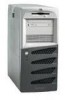
Shelf 5 2nd Hard Drive, Optional, Shelf 3 Backup Tape Drive, Shelf 2 CD-ROM, Shelf 1 FDD
 |
View all HP Tc2100 manuals
Add to My Manuals
Save this manual to your list of manuals |
Page 35 highlights
Chapter 4 Installing Mass Storage Devices 2. Disconnect the power cables and any external cables connected to the Server. If necessary, label each one to expedite re-assembly. 3. Remove the side cover from the Server as described in Chapter 3, "Opening and Closing the HP Server." 4. Disconnect the data and power cables to the existing hard drive in the drive cage. See Figure 4-1. CAUTION Install and remove connectors carefully, and avoid displacing any of the pins in the connector. Shelf 1 (FDD) Shelf 2 (CD-ROM) Shelf 3 (Backup Tape Drive) (Optional) Latch Release (Drive Cage) Shelf 5 (2nd Hard Drive) (Optional) Figure 4-1. Mass Storage Locations 5. Press down and pull out on the latch release of the drive cage located just inside the chassis. See Figures 4-1 and 4-2. 6. Remove the drive cage from the chassis. See Figure 4-2. NOTE If the hard disk drive you are planning to install already has a mounting bracket attached, you must remove it before you can install the drive into the Server. 29
-
 1
1 -
2
-
3
-
4
-
5
-
6
-
7
-
8
-
9
-
10
-
11
-
12
-
13
-
14
-
15
-
16
-
17
-
18
-
19
-
20
-
21
-
22
-
23
-
24
-
25
-
26
-
27
-
28
-
29
-
 30
30 -
 31
31 -
 32
32 -
 33
33 -
 34
34 -
 35
35 -
 36
36 -
 37
37 -
 38
38 -
 39
39 -
 40
40 -
41
-
42
-
43
-
44
-
45
-
46
-
47
-
48
-
49
-
50
-
51
-
52
-
53
-
54
-
55
-
56
-
57
-
58
-
59
-
60
-
61
-
62
-
63
-
64
-
65
-
66
-
67
-
68
-
69
-
70
-
71
-
72
-
73
-
74
-
75
-
76
-
77
-
78
-
79
-
80
-
81
-
82
-
83
-
84
-
85
-
86
-
87
-
88
-
89
-
90
-
91
-
92
-
93
-
94
-
95
-
96
-
97
-
98
-
99
-
100
-
101
-
102
-
103
-
104
-
105
-
106
-
107
 |
 |
