Hitachi L42S504 Owners Guide - Page 14
Side Panel Connections - model
 |
View all Hitachi L42S504 manuals
Add to My Manuals
Save this manual to your list of manuals |
Page 14 highlights
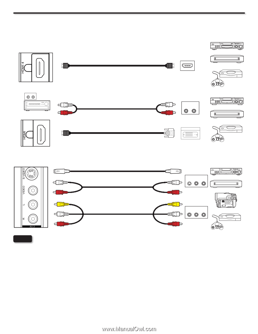
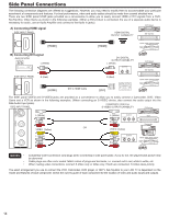
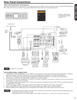
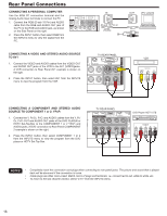
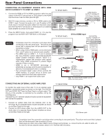
Side Panel Connections The following connection diagrams are offered as suggestions. However, you may need to modify them to accommodate your particular assortment of components and features. For best performance, video and audio cables should be made from coaxial shielded wire. There are two SIDE panel HDMI jacks provided as a convenience to allow you to easily connect HDMI or DVI signals from a DVD, Set-Top-Box, Video Game as shown in the following examples (When a DVI product is connected, the use of a separate audio device is necessary for audio, use an Audio Amplifier and connect to the Audio In jacks). DVD player A) Connecting HDMI signal USB/ SIDE INPUT PANEL HDMI DIGITAL or OUTPUT CAPABILITY Set-Top Box [HDMI] [HDMI] HDMI OUT Home video game system USB/ B) Connecting DVI signal Audio Amplifier 3 AUDIO IN L R L (White) USB/ SIDE INPUT PANEL R (Red) [HDMI] DVI to HDMI Cable DVI DIGITAL OUTPUT CAPABILITY L (White) OUTPUT L R or R (Red) [DVI] DIGITAL OUTPUT DVD player Set-Top Box Home video game system 3 3 The SIDE panel VIDEO and S-VIDEO jacks are provided as a convenience to allow you to easily connect a Camcorder, DVD, Video Game and a VCR as shown in the following examples. (When connecting an S-VIDEO device, also connect the audio output into the Side Audio Input jacks). COMPOSITE VIDEO or SIDE INPUT PANEL S-VIDEO OUTPUT CAPABILITY DVD player L (White) R (Red) VIDEO (Yellow) L (White) R (Red) L (White) OUTPUT S-VIDEO L R VCR R (Red) Camcorder OR VIDEO (Yellow) L (White) OUTPUT VIDEO L R R (Red) Home video game system NOTES • Completely insert connection cord plugs when connecting to side panel jacks. If you do not, the played back picture may be abnormal. • Cable plugs are often color-coded. Match colors of plugs and terminals, i.e. connect red to red, white to white, etc. • When making video connections, connect S-Video only or Video only. If both are connected, S-Video takes priority. The exact arrangement you use to connect the VCR, Camcorder, DVD player, or HDTV Set-Top-Box to your LCD TV is dependent on the model and features of each component. Check the owners guide of each component for the location of video and audio inputs and outputs. 14
-
 1
1 -
2
-
3
-
4
-
5
-
6
-
7
-
8
-
 9
9 -
 10
10 -
 11
11 -
 12
12 -
 13
13 -
 14
14 -
 15
15 -
 16
16 -
 17
17 -
 18
18 -
 19
19 -
20
-
21
-
22
-
23
-
24
-
25
-
26
-
27
-
28
-
29
-
30
-
31
-
32
-
33
-
34
-
35
-
36
-
37
-
38
-
39
-
40
-
41
-
42
-
43
-
44
-
45
-
46
-
47
-
48
-
49
-
50
-
51
-
52
-
53
-
54
-
55
-
56
-
57
-
58
-
59
-
60
 |
 |