Hitachi L42S504 Owners Guide - Page 16
Notes
 |
View all Hitachi L42S504 manuals
Add to My Manuals
Save this manual to your list of manuals |
Page 16 highlights
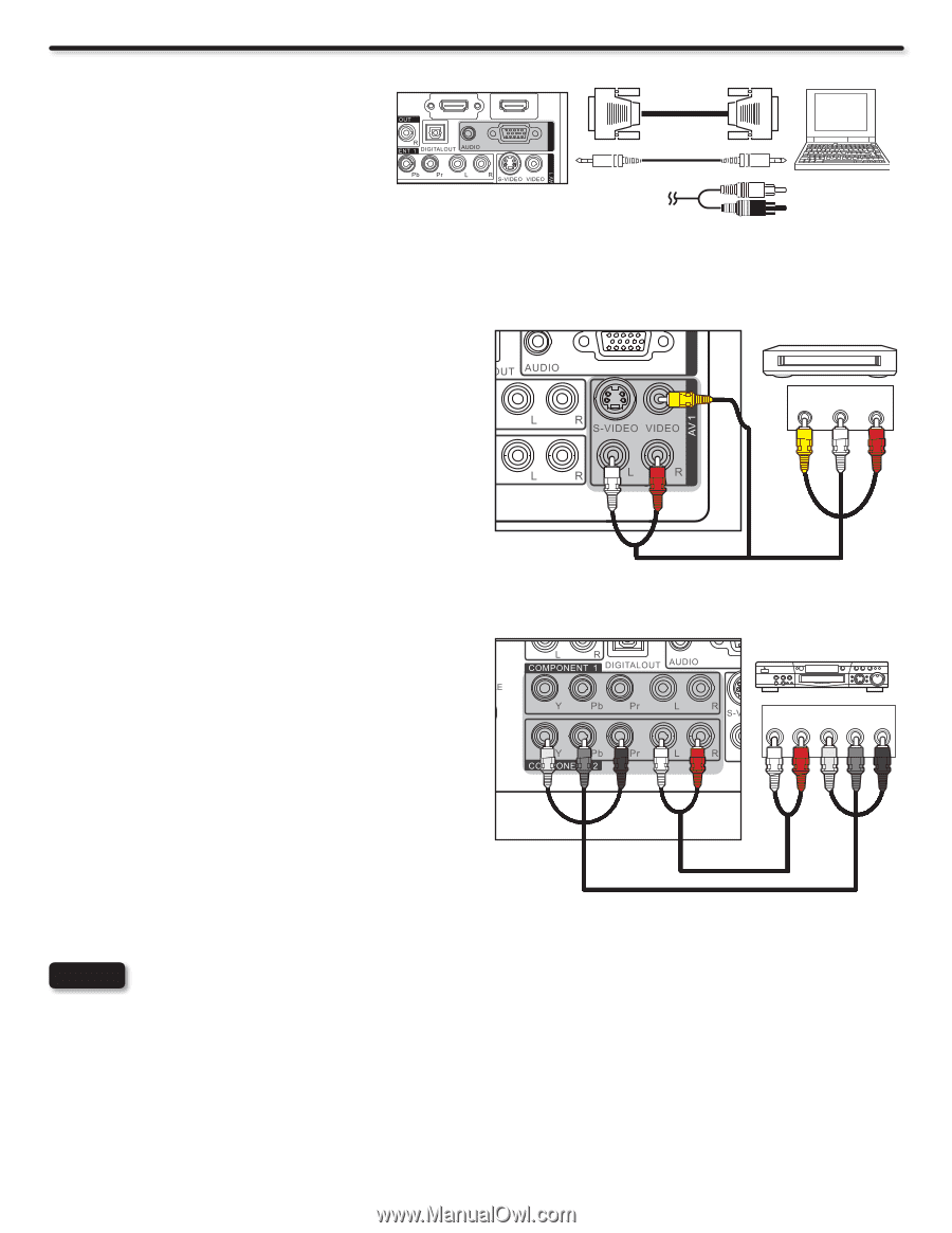
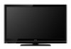
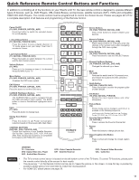
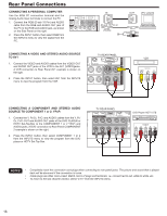
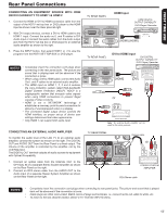
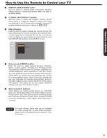
Rear Panel Connections CONNECTING A PERSONAL COMPUTER Use the RGB PC connection terminal and the Analog Audio Input terminals to connect the PC. 1. Connect the RGB (D-sub 15 Pin) and AUDIO cable from the RGB and AUDIO OUT jack of the PC to the RGB and AUDIO jack, as shown on the Side Panel on the right. 2. Press the INPUT button, then select RGB from the INPUTS menu to view the signal from the PC. IN RGB (D-sub 15 Pin) or (Audio) CONNECTING A VIDEO AND STEREO AUDIO SOURCE TO AV1 1. Connect the VIDEO and AUDIO cables from the VIDEO OUT and AUDIO OUT jacks of the VCR to the AV1 (VIDEO)jacks. A VCR connection to Rear Panel AV1 example is shown on the right. 2. Press the INPUT button, then select AV1 from the INPUTS menu to view the program from the VCR. TV REAR PANEL RGB RGB RGB (Yellow) (White) (Red) OUT [PC sample] DVD player VVCCRR CamOcUoTrdPeUrT VIDEO L R Home video game system CONNECTING A COMPONENT AND STEREO AUDIO SOURCE TO COMPONENT 1 or 2: YPbPr de Dolby 1. Connect the Y, Pb/Cb, Pr/Cr and AUDIO cables from the Y, Pb/ Cb, Pr/Cr OUT and AUDIO OUT jacks of the DVD PLAYER or HDTV Set-Top-Box to the COMPONENT 1 or 2 YPbPr and AUDIO jacks. A DVD connection to Rear Panel COMPONENT 2 example is shown on the right. 2. Press the INPUT button, then select COMPONENT 1 or 2 from the INPUTS menu to view the program from the DVD player or HDTV Set-Top Box. TV REAR PANEL DVD PlaDyVeDr/pHlayDeTr V STB VCR Output L R Y PB PR Camcorder White Red Green Blue Red Home video game system NOTES • Completely insert the connection cord plugs when connecting to rear panel jacks. The picture and sound that is played back will be abnormal if the connection is loose. • Cable plugs are often color-coded. Match colors of plugs and terminals, i.e. connect red to red, white to white, etc. • To return to the last channel viewed, select "0.TV" from the INPUTS menu. 16
-
 1
1 -
2
-
3
-
4
-
5
-
6
-
7
-
8
-
9
-
10
-
 11
11 -
 12
12 -
 13
13 -
 14
14 -
 15
15 -
 16
16 -
 17
17 -
 18
18 -
 19
19 -
 20
20 -
 21
21 -
22
-
23
-
24
-
25
-
26
-
27
-
28
-
29
-
30
-
31
-
32
-
33
-
34
-
35
-
36
-
37
-
38
-
39
-
40
-
41
-
42
-
43
-
44
-
45
-
46
-
47
-
48
-
49
-
50
-
51
-
52
-
53
-
54
-
55
-
56
-
57
-
58
-
59
-
60
 |
 |