IBM 8487 User Manual - Page 47
backplane is the printed circuit board behind the bay. The backplane controls
 |
UPC - 000435687531
View all IBM 8487 manuals
Add to My Manuals
Save this manual to your list of manuals |
Page 47 highlights
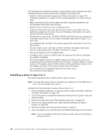
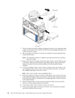
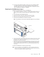
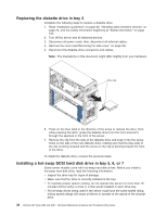
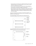
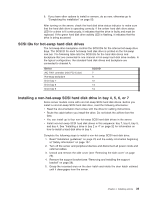
v You do not have to turn off the server to install hot-swap drives in the hot-swap drive bays; however, you may need to restart the server so that the hot-swap drive will be recognized and reconfigured. v Install hot-swap hard disk drives in this sequence: bay 7, bay 6, and bay 5. v If the server has an optional RAID adapter, see the documentation that comes with the adapter for instructions for installing a hard disk drive. v Each hot-swap drive has two LEDs: the hard disk drive activity LED and the hard disk drive status LED. When the green hard disk drive activity LED is flashing, it indicates that the controller is accessing the hard disk drive. When the amber hard disk drive status LED is lit continuously, it indicates that the drive is faulty and must be replaced. The server hot-swap bays are connected to a hard disk drive backplane. This backplane is the printed circuit board behind the bay. The backplane controls the SCSI IDs for the hot-swap drives. The following illustration shows the location of the components on the hot-swap-drive backplane as seen from the front of the server drive cage. Hard disk drive activity LED (green) Hard disk drive status LED (amber) SCSI hot-swap hard disk drive connector The following illustration shows the rear connectors on the hot-swap-drive backplane as seen from the rear of the server drive cage. SCSI cable connector SCSI power cable connector I2C cable connector Chapter 4. Installing options 37
-
 1
1 -
2
-
3
-
4
-
5
-
6
-
7
-
8
-
9
-
10
-
11
-
12
-
13
-
14
-
15
-
16
-
17
-
18
-
19
-
20
-
21
-
22
-
23
-
24
-
25
-
26
-
27
-
28
-
29
-
30
-
31
-
32
-
33
-
34
-
35
-
36
-
37
-
38
-
39
-
40
-
41
-
 42
42 -
 43
43 -
 44
44 -
 45
45 -
 46
46 -
 47
47 -
 48
48 -
 49
49 -
 50
50 -
 51
51 -
 52
52 -
53
-
54
-
55
-
56
-
57
-
58
-
59
-
60
-
61
-
62
-
63
-
64
-
65
-
66
-
67
-
68
-
69
-
70
-
71
-
72
-
73
-
74
-
75
-
76
-
77
-
78
-
79
-
80
-
81
-
82
-
83
-
84
-
85
-
86
-
87
-
88
-
89
-
90
-
91
-
92
-
93
-
94
-
95
-
96
-
97
-
98
-
99
-
100
-
101
-
102
-
103
-
104
-
105
-
106
-
107
-
108
-
109
-
110
-
111
-
112
-
113
-
114
-
115
-
116
-
117
-
118
-
119
-
120
-
121
-
122
-
123
-
124
-
125
-
126
-
127
-
128
-
129
-
130
-
131
-
132
-
133
-
134
-
135
-
136
-
137
-
138
-
139
-
140
-
141
-
142
-
143
-
144
-
145
-
146
-
147
-
148
-
149
-
150
-
151
-
152
-
153
-
154
-
155
-
156
-
157
-
158
-
159
-
160
 |
 |
