IBM 8487 User Manual - Page 54
Installing an adapter, The optional IBM Remote Supervisor Adapter II can be installed only in PCI-X
 |
UPC - 000435687531
View all IBM 8487 manuals
Add to My Manuals
Save this manual to your list of manuals |
Page 54 highlights
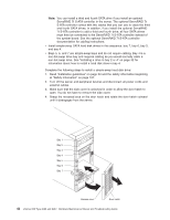
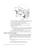
connector on the system board. Each Serial ATA drive comes with a cable. If you install an additional Serial ATA drive, you will need an additional cable. If you install the optional ServeRAID 7t S-ATA controller to add a third and fourth SATA drive, all four SATA drives must then be connected to the ServeRAID 7t S-ATA controller instead of the system board. The optional ServeRAID 7t S-ATA controller comes with two cables that you can use to cable the third and fourth SATA drives. - SCSI: A round SCSI cable connects SCSI devices to the integrated SCSI controller with RAID capabilities on the system board. - A round SCSI cable connects external SCSI devices to the integrated SCSI controller with RAID capabilities on the system board. For more information about connecting SCSI devices, see the SCSI documentation. - An Ultra320 twisted ribbon cable connects the internal Ultra320 SCSI hard disk drive to the SCSI connector on the system board. This cable has four additional connectors for attaching more internal SCSI devices. For hot-swap models, the maximum cable length that supports Ultra320 SCSI hard disk drives is 40 cm (16 in.). Installing an adapter The following notes describe the types of adapters that the server supports and other information that you must consider when installing an adapter. v Locate the documentation that comes with the adapter and follow those instructions in addition to the instructions in this section. If you need to change the switch settings or jumper settings on the adapter, follow the instructions that come with the adapter. v Read the documentation that comes with the operating system. v The server comes with five PCI slots. v The standard SCSI adapter is installed in the mini-PCI-X slot. v You can install full-length adapters in all five PCI slots. v You can install only 32-bit adapters in the 32-bit PCI slots 3 through 5 and 64-bit adapters in the 64-bit PCI-X slots 1 and 2. Note: An illustration showing the numbering of the PCI slots can be found at "System-board option connectors" on page 69. v The 32-bit PCI slots 3 through 5 support 5.0 V signaling PCI adapters; they do not support 3.3 V signaling adapters. However, 64-bit adapters are supported if they are universal adapters. v The 64-bit PCI-X slots 1 and 2 support 3.3 V signaling PCI or PCI-X adapters; they do not support 5.0 V signaling adapters. v The PCI bus configuration is as follows: - The 32-bit PCI slots 3 through 5 and the onboard ATI 7000M video adapter are on the 33 MHz PCI bus. - The 64-bit PCI-X slots 1 and 2 and the mini-PCI-X slot are on the 66 MHz PCI-X bus. v The optional IBM Remote Supervisor Adapter II can be installed only in PCI-X slot 2. Use the ribbon cable that comes with this adapter to connect it to the Remote Supervisor Adapter II connector on the system board. v If you install the optional IBM Remote Supervisor Adapter II, you must disconnect the video cable from the system board and connect it to the optional Remote Supervisor Adapter II. 44 xSeries 206 Type 8482 and 8487: Hardware Maintenance Manual and Troubleshooting Guide
-
 1
1 -
2
-
3
-
4
-
5
-
6
-
7
-
8
-
9
-
10
-
11
-
12
-
13
-
14
-
15
-
16
-
17
-
18
-
19
-
20
-
21
-
22
-
23
-
24
-
25
-
26
-
27
-
28
-
29
-
30
-
31
-
32
-
33
-
34
-
35
-
36
-
37
-
38
-
39
-
40
-
41
-
42
-
43
-
44
-
45
-
46
-
47
-
48
-
 49
49 -
 50
50 -
 51
51 -
 52
52 -
 53
53 -
 54
54 -
 55
55 -
 56
56 -
 57
57 -
 58
58 -
 59
59 -
60
-
61
-
62
-
63
-
64
-
65
-
66
-
67
-
68
-
69
-
70
-
71
-
72
-
73
-
74
-
75
-
76
-
77
-
78
-
79
-
80
-
81
-
82
-
83
-
84
-
85
-
86
-
87
-
88
-
89
-
90
-
91
-
92
-
93
-
94
-
95
-
96
-
97
-
98
-
99
-
100
-
101
-
102
-
103
-
104
-
105
-
106
-
107
-
108
-
109
-
110
-
111
-
112
-
113
-
114
-
115
-
116
-
117
-
118
-
119
-
120
-
121
-
122
-
123
-
124
-
125
-
126
-
127
-
128
-
129
-
130
-
131
-
132
-
133
-
134
-
135
-
136
-
137
-
138
-
139
-
140
-
141
-
142
-
143
-
144
-
145
-
146
-
147
-
148
-
149
-
150
-
151
-
152
-
153
-
154
-
155
-
156
-
157
-
158
-
159
-
160
 |
 |
