IBM 8487 User Manual - Page 57
Installing a security rope clip, Complete the following steps to install a rope clip
 |
UPC - 000435687531
View all IBM 8487 manuals
Add to My Manuals
Save this manual to your list of manuals |
Page 57 highlights
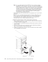
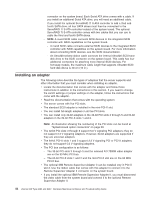
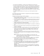
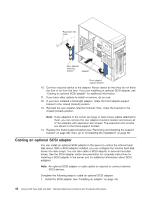
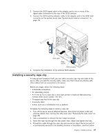
2. Connect the SCSI signal cable to the adapter and to one or more of the signal-cable connectors to the rear of the SCSI devices. 3. Connect the SCSI-activity-indicator cable to the adapter and to the SCSI LED connector on the system board (see "System-board internal connectors" on page 70). SCSI cable RAID adapter SCSI connector 4. Complete the installation of the optional SCSI adapter. Installing a security rope clip To help prevent hardware theft, you can add a security rope clip and cable to the server. After you add the security cable, make sure that it does not interfere with other cables that are connected to the server. Before you begin, obtain the following items: v A flat-blade screwdriver v An adjustable wrench v A 19 mm (0.75 in.) rope clip or wire rope (similar to National Manufacturing number 3230, stock number 176-735) v Threaded nuts that fit the rope clip v A security cable v A lock, such as a combination lock or padlock Complete the following steps to install a rope clip: 1. Turn off the server and all attached devices. Disconnect all power cords and external cables; then, remove the side cover (see "Removing the side cover" on page 26). 2. Use a screwdriver to remove the two metal knockouts. 3. Insert the rope clip through the rear panel; then, attach and tighten the nuts. 4. Thread the cable through the rope clip and around an object that is not part of or permanently secured to the building structure or foundation, and from which Chapter 4. Installing options 47
-
 1
1 -
2
-
3
-
4
-
5
-
6
-
7
-
8
-
9
-
10
-
11
-
12
-
13
-
14
-
15
-
16
-
17
-
18
-
19
-
20
-
21
-
22
-
23
-
24
-
25
-
26
-
27
-
28
-
29
-
30
-
31
-
32
-
33
-
34
-
35
-
36
-
37
-
38
-
39
-
40
-
41
-
42
-
43
-
44
-
45
-
46
-
47
-
48
-
49
-
50
-
51
-
 52
52 -
 53
53 -
 54
54 -
 55
55 -
 56
56 -
 57
57 -
 58
58 -
 59
59 -
 60
60 -
 61
61 -
 62
62 -
63
-
64
-
65
-
66
-
67
-
68
-
69
-
70
-
71
-
72
-
73
-
74
-
75
-
76
-
77
-
78
-
79
-
80
-
81
-
82
-
83
-
84
-
85
-
86
-
87
-
88
-
89
-
90
-
91
-
92
-
93
-
94
-
95
-
96
-
97
-
98
-
99
-
100
-
101
-
102
-
103
-
104
-
105
-
106
-
107
-
108
-
109
-
110
-
111
-
112
-
113
-
114
-
115
-
116
-
117
-
118
-
119
-
120
-
121
-
122
-
123
-
124
-
125
-
126
-
127
-
128
-
129
-
130
-
131
-
132
-
133
-
134
-
135
-
136
-
137
-
138
-
139
-
140
-
141
-
142
-
143
-
144
-
145
-
146
-
147
-
148
-
149
-
150
-
151
-
152
-
153
-
154
-
155
-
156
-
157
-
158
-
159
-
160
 |
 |
