Intel SC5600BASE Service Guide - Page 22
Intel, Local Control Panel
 |
View all Intel SC5600BASE manuals
Add to My Manuals
Save this manual to your list of manuals |
Page 22 highlights
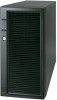
Server Chassis Features Descriptions of the front control panel LEDs are listed in the following table. See your server/workstation documentation for functionality of the buttons. LED Name Table 4. Front Control Panel LED Descriptions Color Condition Description Power LED Green Green System LED Status Amber Off Hard Drive Activity Green NIC1 Activity Green NIC2 Activity ID LED Green Blue On Off On Blink On Blink Off Off Blink On Blink Off On Blink Off Blink On Power on Power off System booted and ready System ready, but degraded: some CPU fault, DIMM killed, and so forth Critical alarm: Critical power module failure, critical fan failure, voltage (power supply), voltage, thermal fault, and so forth Non-critical failure: Redundant fan failure, redundant power failure, non-critical power and voltage, and so forth AC Power off; Powered Down (DC-off state or S5), and no degraded, non-critical, critical conditions exist* Hard drive activity Linked LAN activity Idle Linked LAN activity Idle Server identification; toggled by ID button or software Server identification; toggled by ID button or software * When the server is powered down (transitions to the DC-off state or S5), the BMC is still on standby power and retains the sensor and front panel status LED state established before the power-down event. If the system status is normal when the system is powered down (the LED is in a solid green state), the system status LED will be off. Intel® Local Control Panel The optional Intel® Local Control Panel provides enhanced system control by using a LCD display, which provides additional controls and indicators beyond the standard control panel. The following figure shows the features available on the Intel® Local Control Panel. 8 Intel® Server Chassis SC5600 Service Guide
-
 1
1 -
2
-
3
-
4
-
5
-
6
-
7
-
8
-
9
-
10
-
11
-
12
-
13
-
14
-
15
-
16
-
 17
17 -
 18
18 -
 19
19 -
 20
20 -
 21
21 -
 22
22 -
 23
23 -
 24
24 -
 25
25 -
 26
26 -
 27
27 -
28
-
29
-
30
-
31
-
32
-
33
-
34
-
35
-
36
-
37
-
38
-
39
-
40
-
41
-
42
-
43
-
44
-
45
-
46
-
47
-
48
-
49
-
50
-
51
-
52
-
53
-
54
-
55
-
56
-
57
-
58
-
59
-
60
-
61
-
62
-
63
-
64
-
65
-
66
-
67
-
68
-
69
-
70
-
71
-
72
-
73
-
74
-
75
-
76
-
77
-
78
-
79
-
80
-
81
-
82
-
83
-
84
-
85
-
86
-
87
-
88
-
89
-
90
-
91
-
92
-
93
-
94
-
95
-
96
-
97
-
98
-
99
-
100
-
101
-
102
-
103
-
104
-
105
-
106
-
107
-
108
-
109
-
110
-
111
-
112
-
113
-
114
-
115
-
116
-
117
-
118
 |
 |
