Invacare M91 Owners Manual
Invacare M91 Manual
 |
View all Invacare M91 manuals
Add to My Manuals
Save this manual to your list of manuals |
Invacare M91 manual content summary:
- Invacare M91 | Owners Manual - Page 1
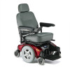
Owner's Operator and Maintenance Manual Pronto® M91™ with SureStep® DEALER: This manual MUST be given to the user of the wheelchair. USER: BEFORE using this wheelchair, read this manual and save for future reference. For more information regarding Invacare products, parts, and services, please visit - Invacare M91 | Owners Manual - Page 2
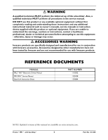
for use with Invacare products. REFERENCE DOCUMENTS MANUAL MK5™NX™Electronic Owner Manual M91/M94™Service Manual Quad Link Instruction Sheet PART NUMBER 1110532 1125038 1134844 NOTE: Updated versions of this manual are available on www.invacare.com. Pronto® M91™ with SureStep® 2 Part No - Invacare M91 | Owners Manual - Page 3
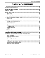
M91 Standard...9 M91 Heavy Duty...10 All Wheelchairs...10 TYPICAL PRODUCT PARAMETERS 11 PRONTO M91...11 SECTION 1-GENERAL GUIDELINES 13 Controller Settings/Repair or Service 13 Accessories Information ...13 Operation Information ...13 Batteries...15 Charging Batteries ...15 Grounding Instructions - Invacare M91 | Owners Manual - Page 4
Troubleshooting Guide ...28 Troubleshooting - Electrical...29 Information Gauge Display Diagnostics 29 Service Indicator Light Diagnostics 29 Checking Battery Charge Level...30 SECTION 5-WHEELCHAIR OPERATION 31 Operating the Wheelchair...31 Turning the Power On/Off ...31 On/Off Button ...31 Using - Invacare M91 | Owners Manual - Page 5
...52 Composite...52 Articulating...52 Installing/Removing Elevating Legrests 53 Installing...53 Removing ...53 Raising/Lowering Elevating Legrests and/or Adjusting Calfpads 54 Raising/Lowering Elevating Legrests 54 Adjusting Calfpads...54 Part No 1141450 5 Pronto® M91™ with SureStep® - Invacare M91 | Owners Manual - Page 6
at warranty.invacare.com Please have your model number and purchase date available to complete your registration. Any registration information you submit will only be used by Invacare Corporation and protected as required by applicable laws and regulations. Pronto® M91™ with SureStep® 6 Part No - Invacare M91 | Owners Manual - Page 7
that can safely be made by the user. If there is a procedure or adjustment that needs to be performed on the seating system that is not in this manual, do not perform that procedure. Have the seating system serviced by a qualified technician. Part No 1141450 7 Pronto® M91™ with SureStep® - Invacare M91 | Owners Manual - Page 8
other chairs previously used. This Power Wheelchair has Invacare's SureStep technology, a feature that provides the wheelchair with optimum traction and stability when driving forward over transitions and thresholds of up to 3-inches. The following warnings apply specifically to the SureStep Feature - Invacare M91 | Owners Manual - Page 9
LABEL LOCATIONS LABEL LOCATIONS M91 Standard Serial Number Label is located on a plate on the inside of the right rear frame. Part No 1141450 9 Pronto® M91™ with SureStep® - Invacare M91 | Owners Manual - Page 10
LABEL LOCATIONS M91 Heavy Duty Serial Number Label is located on a plate on the inside of the right rear frame. All Wheelchairs NOTE: Auto style seat positioning strap shown. This label is also on the airline style seat positioning strap. Pronto® M91™ with SureStep® 10 Part No 1141450 - Invacare M91 | Owners Manual - Page 11
DRIVE WHEELS/TIRES: CASTERS: FOOTRESTS/LEGRESTS: WEIGHT W/SEATING SYSTEM AND ACCESSORIES W/O BATTERIES: W/BATTERIES: SHIPPING: ARMRESTS: BATTERIES: INCLINE CAPABILITY: PERFORMANCE SPEED Standard: Heavy Duty: TURNING RADIUS: *RANGE (VARIABLE) Standard: Heavy Duty: **WEIGHT LIMITATION Standard: Heavy - Invacare M91 | Owners Manual - Page 12
with the battery discharge indicator on the joystick to determine the range of their wheelchair. Refer to Battery Charger Operation on page 65 for more information about the battery discharge indicator. **NOTE: Refer to Stability and Balance on page 20. Pronto® M91™ with SureStep® 12 Part No - Invacare M91 | Owners Manual - Page 13
your weight in the direction you are turning. DO NOT shift your weight in the opposite direction of the turn. Shifting your weight in the opposite direction of the turn may cause the inside drive wheel to lose traction and the wheelchair to tip over. Part No 1141450 13 Pronto® M91™ with SureStep® - Invacare M91 | Owners Manual - Page 14
on the frame of the wheelchair. DO NOT stand on the footplates/footboard. When getting in or out of the wheelchair, make sure that the footboard or footplates are in the upward position or swing the footrests towards the outside of the wheelchair. Pronto® M91™ with SureStep® 14 Part No 1141450 - Invacare M91 | Owners Manual - Page 15
be replaced IMMEDIATELY. Avoid storing or using the wheelchair near open flame or combustible products. Serious injury or damage to property may result. Batteries The warranty and performance specifications contained in this manual are based on the use of deep cycle gel cell batteries. Invacare - Invacare M91 | Owners Manual - Page 16
his/her power wheelchair from a rain storm and retain wheelchair operation. DO NOT leave power wheelchair in a rain storm of any kind. DO NOT use power wheelchair in a shower. DO NOT store power wheelchair in a damp area for an extended period of time. Pronto® M91™ with SureStep® 16 Part No - Invacare M91 | Owners Manual - Page 17
a weight training apparatus, Invacare shall NOT be liable for bodily injury and the warranty is void. Weight Limitation The Pronto M91 wheelchairs have the following weight limitations: MODEL WEIGHT LIMITATION STANDARD HEAVY DUTY 300 lb 400 lb Part No 1141450 17 Pronto® M91™ with SureStep® - Invacare M91 | Owners Manual - Page 18
POWERED WHEELCHAIR. Electromagnetic Interference (EMI) From Radio Wave Sources Powered wheelchairs and motorized scooters (in this text, both will be referred to as powered wheelchairs , are not likely to cause EMI problems to your powered wheelchair. Pronto® M91™ with SureStep® 18 Part No 1141450 - Invacare M91 | Owners Manual - Page 19
very close to the powered wheelchair's control system while using these devices. This can affect powered wheelchair movement and braking. to the electronics of this wheelchair as manufactured by Invacare may adversely affect the EMI immunity levels. Part No 1141450 19 Pronto® M91™ with SureStep® - Invacare M91 | Owners Manual - Page 20
only as a "basic" guide. The techniques that are discussed on the following pages have been used successfully by many. Individual wheelchair users often develop skills to deal with daily living activities that may differ from those described in this manual. Invacare recognizes and encourages each - Invacare M91 | Owners Manual - Page 21
several combinations in the presence of a qualified healthcare professional before attempting active use of the wheelchair. The Pronto M91 wheelchairs have the following weight limitations: STANDARD HEAVY DUTY MODEL WEIGHT LIMITATION 300 lb 400 lb To assure stability and proper operation of your - Invacare M91 | Owners Manual - Page 22
used to move the wheelchair or as lifting supports, as they may be inadvertently released, resulting in possible injury to the user and/or assistant(s). When learning a new assistance technique, have an experienced assistant help you before attempting it alone. Pronto® M91™ with SureStep® 22 Part - Invacare M91 | Owners Manual - Page 23
forks as hand hold supports, transfer the wheelchair base to the desired location. FIGURE 3.4 Lifting/Stairways - Hand Hold Supports ƽ WARNING: ESCALATORS DO NOT use an escalator to move a wheelchair between floors. Serious bodily injury may occur. Part No 1141450 23 Pronto® M91™ with SureStep® - Invacare M91 | Owners Manual - Page 24
Flip back or remove arm on side of wheelchair you are transferring from. 4. Shift body weight into seat with transfer. ƽ WARNING During independent transfer, little or no seat platform will be beneath you. Use a transfer board if at all possible. Pronto® M91™ with SureStep® 24 Part No 1141450 - Invacare M91 | Owners Manual - Page 25
SECTION 3-SAFETY/HANDLING OF WHEELCHAIRS Reaching, Leaning and Bending - Forward ƽ WARNING DO NOT attempt to reach objects if you have to move forward in the seat or pick them up from the floor position. FIGURE 3.7 Reaching and Bending - Backward Part No 1141450 25 Pronto® M91™ with SureStep® - Invacare M91 | Owners Manual - Page 26
against arm tubes. ❑ Ensure seat is secured to wheelchair frame. ❑ Ensure seat release latch is functional. Replace if necessary. ❑ Ensure wheel mounting nuts are secure on drive wheels. ❑ Ensure there is no excessive side movement or binding when drive wheels are lifted and spun when disengaged - Invacare M91 | Owners Manual - Page 27
arm tubes. ❑ Ensure seat and/or back upholstery have no rips and do not sag. Replace if necessary. ❑ Inspect electrical components for signs of corrosion. Replace if corroded or damaged. ❑ Ensure seat release latch is not worn. Replace if necessary. Part No 1141450 27 Pronto® M91™ with SureStep® - Invacare M91 | Owners Manual - Page 28
™electronics owner's manual supplied with wheelchair). Have terminals cleaned. Contact Dealer/Invacare for service. NOTE: For additional troubleshooting information and explanation of error codes, refer to the Electronics Manual supplied with each wheelchair. Pronto® M91™ with SureStep® 28 Part - Invacare M91 | Owners Manual - Page 29
the batteries. Refer to Charging Batteries on page 64. Check that battery cables are connected properly. Refer to Connecting/Disconnecting the Battery Wiring Harness on page 62. If necessary, replace batteries. Refer to Charging Batteries on page 64. Part No 1141450 29 Pronto® M91™ with SureStep® - Invacare M91 | Owners Manual - Page 30
strap to remove, move or install a battery. Don't tap on clamps and terminals with tools. Push battery clamps on the terminals. Spread clamps wider if necessary. Don't mismatch your battery and chargers. Use ONLY a GEL charger for a GEL battery. Pronto® M91™ with SureStep® 30 Part No 1141450 - Invacare M91 | Owners Manual - Page 31
of operation. The joystick is spring‐loaded, and automatically returns to the upright (neutral) position when released. Pushing the joystick in a given direction causes the wheelchair to move in that direction. Part No 1141450 31 Pronto® M91™ with SureStep® - Invacare M91 | Owners Manual - Page 32
the joystick. Move the joystick RIGHT. Move the joystick LEFT. Release the joystick and the wheelchair will quickly slow down. To Move Forward On/Off Button To Move Right Joystick To Move Left To Move Backward FIGURE 5.2 Operating the Wheelchair Pronto® M91™ with SureStep® 32 Part No 1141450 - Invacare M91 | Owners Manual - Page 33
mode. Speed limit mode limits the drive speed to a pre‐ programmed value, typically when the seat has been elevated and the wheelchair is required to drive at 20% speed. Speed Control Buttons The speed control buttons (tortoise button ( ) and hare button ( )) are used to set and adjust the maximum - Invacare M91 | Owners Manual - Page 34
system diagnostic device when a fault is detected by the control module. A specific number of flashes of the LEDs indicate the type of fault detected. Refer to Troubleshooting Guide on page 28 for the diagnostic indications of the wheelchair status. Pronto® M91™ with SureStep® 34 Part No 1141450 - Invacare M91 | Owners Manual - Page 35
one of four positions. 3. Reinstall the socket screw that secures the armrest to the seat frame assembly and tighten securely. DETAIL "B" - HEIGHT Height Adjustment Holes Seat Frame Assembly Lock Knob Armrest FIGURE 6.1 Adjusting Van Seat Armrests Part No 1141450 35 Pronto® M91™ with SureStep® - Invacare M91 | Owners Manual - Page 36
the Seat Assembly ƽ WARNING DO NOT store items under seat - interference with seat latch may result. NOTE: For this procedure, refer to FIGURE 7.3 on page 37. Removing 1. Disconnect the joystick. Refer to Disconnecting/Connecting the MK5 Joysticks on page 69. Pronto® M91™ with SureStep® 36 Part - Invacare M91 | Owners Manual - Page 37
seat can be adjusted to five height positions in ½‐inch increments. 1. Remove the seat. Refer to Removing/Installing the Seat Assembly on page 36. 2. Remove the mounting screw and locknut that secures the adjustable height tube to the support tube. Part No 1141450 37 Pronto® M91™ with SureStep - Invacare M91 | Owners Manual - Page 38
adjustable height tubes. ƽ WARNING When reinstalling the seat verify that the seat brackets are engaged with the seat clevis pins by pulling up on the latch bar. 6. Reinstall the seat. Refer to Removing/Installing the Seat Assembly on page 36. Pronto® M91™ with SureStep® 38 Part No 1141450 - Invacare M91 | Owners Manual - Page 39
Holes for Standard Seat Position Use these Mounting Holes for Standard Seat Position Rear of Seat *NOTE: Only the 22‐inch wide seats have these mounting holes. DO NOT use these mounting holes. FIGURE 7.5 Adjusting Seat Position on Seat Frame Part No 1141450 39 Pronto® M91™ with SureStep® - Invacare M91 | Owners Manual - Page 40
16 X 18 inch 17 inch 18 X 18 inch 19 inch 20 X 20 inch 19 inch 22 X 20 inch Maximum Seat Depth Seat Depth Seat Size 18 inch 16 X 18 inch 18 inch 18 X 18 inch 20 inch 20 X 20 inch 20 inch 22 X 20 inch FIGURE 7.6 Adjusting Seat Depth Pronto® M91™ with SureStep® 40 Part No 1141450 - Invacare M91 | Owners Manual - Page 41
straps to the seat frame. Securely tighten. Seat Frame Rear of Seat Frame Seat Assembly Seat Positioning Strap Washer Seat Positioning Strap Front of Seat Frame Mounting Screws Washer Seat Rail FIGURE 7.7 Replacing the Seat Positioning Strap Part No 1141450 41 Pronto® M91™ with SureStep® - Invacare M91 | Owners Manual - Page 42
hole in the footboard assembly. 2. Install the quick release pin by depressing the button while sliding the pin in. Ensure that the detent balls of the quick release pin are fully released and protruding past the outer edge of the tube (Detail "A"). Pronto® M91™ with SureStep® 42 Part No 1141450 - Invacare M91 | Owners Manual - Page 43
Mounting Hole Wheelchair Frame SECTION 8-FOOTBOARD ASSEMBLY Quick Release Pin DETAIL "A" - BOTTOM VIEW OF FOOTBOARD Quick Release Pin place. Set Screw, Washer and Jam Nut Footboard Assembly FIGURE 8.2 Adjusting the Footboard Assembly - Angle Part No 1141450 43 Pronto® M91™ with SureStep® - Invacare M91 | Owners Manual - Page 44
the wheelchair frame. ƽ WARNING Make sure the Wheelchair Frame DETAIL "A" - BOTTOM VIEW OF FOOTBOARD Quick Release Pin Quick Release Pin Detent Ball Footboard Assembly Outer Edge of Tube Detent Balls FIGURE 8.3 Adjusting the Footboard Assembly - Depth Pronto® M91™ with SureStep® 44 Part - Invacare M91 | Owners Manual - Page 45
into place. NOTE: The footplate will be on the inside of the wheelchair when locked in place. 5. Repeat STEPS 1‐4 for opposite side of wheelchair. 6. To Remove the footrests, push the front rigging release lever inward and rotate the footrest out. Part No 1141450 45 Pronto® M91™ with SureStep® - Invacare M91 | Owners Manual - Page 46
bolt, coved washers and locknut that secure lower footrest to footrest support. Tighten securely. FIGURE 9.3 Adjusting Footrest Height Model PHWH93, PW93 and 70° 6. Repeat STEPS 1‐5 for the opposite side of the wheelchair footrest, if necessary. Pronto® M91™ with SureStep® 46 Part No 1141450 - Invacare M91 | Owners Manual - Page 47
FIGURE 9.5 Adjusting Footrest Height Model PH904A and PHAL4A 3. Securely tighten the lug bolt and locknut that secure the lower footrest to the footrest support. 4. Repeat STEPS 1‐3 for the opposite side of the wheelchair footrest, if necessary. Part No 1141450 47 Pronto® M91™ with SureStep® - Invacare M91 | Owners Manual - Page 48
the outside of the wheelchair facing away from the seat frame. 1. Remove the seat. Refer to Removing/Installing the Seat Assembly on page 36. 2. Remove the two socket bolts and locknuts that secure telescoping front rigging support to the seat frame. Pronto® M91™ with SureStep® 48 Part No 1141450 - Invacare M91 | Owners Manual - Page 49
Replacing ‐ Perform the following steps: i. Remove the existing telescoping front rigging support from the wheelchair frame. ii. Insert the new telescoping front rigging support into the seat Adjusting/Replacing Telescoping Front Rigging Supports Part No 1141450 49 Pronto® M91™ with SureStep® - Invacare M91 | Owners Manual - Page 50
Adjustable Angle Flip‐Up Footplates on page 51. 90° Footrest Support Flat Screw Footplate Footplate Hinge Half Clamp Washer Locknut Nylon Adjustment Screw Half Clamp Footplate Hinge FIGURE 9.9 Installing Adjustable Angle Flip-up Footplates Pronto® M91™ with SureStep® 50 Part No 1141450 - Invacare M91 | Owners Manual - Page 51
(FIGURE 9.9). Footrest Support Footplate Side View of Footplate and Footrest Support 2. Position the footrest assembly or the desired inversion or eversion is obtained (FIGURE 9.11). FIGURE 9.11 Perpendicular and/or Inversion/Eversion Adjustment Part No 1141450 51 Pronto® M91™ with SureStep - Invacare M91 | Owners Manual - Page 52
of footrest assembly. Articulating Articulating Mounting Screw 1. Remove the two mounting screws that secure the heel loop to the articulating footplate. Heel Loop Articulating Footplate FIGURE 9.12 Composite/Articulating Footplate Heel Loop Replacement Pronto® M91™ with SureStep® 52 Part No - Invacare M91 | Owners Manual - Page 53
of the wheelchair) and swing the legrest to the outside of the wheelchair. 2. Lift up on the legrest and remove from the wheelchair. 3. Repeat STEPS 1‐ 2 for opposite side of wheelchair. Bolt/Nut FIGURE 9.13 Installing/Removing Elevating Legrests Part No 1141450 53 Pronto® M91™ with SureStep® - Invacare M91 | Owners Manual - Page 54
used, the legrest will need to be raised to avoid interference with the front stabilizers while going over obstacles or going UP and down ramps. Refer to Raising/Lowering Elevating Legrests on page 54. 3. Turn the calfpad towards the inside of the wheelchair. Pronto® M91™ with SureStep® 54 Part - Invacare M91 | Owners Manual - Page 55
adjustment or service verify that On/Off switch on the joystick is in the Off position. Replacing the Flat Free Tires on the Wheel Rim ƽ WARNING DO NOT attempt to replace flat free tires. This procedure MUST be performed by a qualified technician. NOTE: During initial use of the wheelchair, the user - Invacare M91 | Owners Manual - Page 56
SECTION 10-SHROUD/WHEELS Installing 1. Perform one of the following: • Top Shroud ‐ Rear of Wheelchair Base Frame Seat Supports Hook and Loop Strips Front of Wheelchair Release Knob FIGURE 10.1 Removing/Installing the Shrouds Front Shroud Pronto® M91™ with SureStep® 56 Part No 1141450 - Invacare M91 | Owners Manual - Page 57
the motors to drive the wheels. Detail "A" Motor Release Lever Towards Center of Wheelchair Towards Outside of Wheelchair Motor Locks Disengaged (Freewheel Mode) Motor Locks Engaged (Drive Mode) FIGURE 10.2 Engaging/Disengaging Motor Release Lever Part No 1141450 57 Pronto® M91™ with SureStep® - Invacare M91 | Owners Manual - Page 58
repeat STEPS 1‐3 until correct. FIGURE 10.4 Adjusting Forks 5. Snap dust cover into the caster headtube ensuring that the tabs are under the plastic side shrouds. NOTE: Components exploded for clarity. There is no need to remove the fork from the base frame. Pronto® M91™ with SureStep® 58 Part - Invacare M91 | Owners Manual - Page 59
existing or new battery(ies), clean the baking soda from the battery tray or battery(ies) being sure to avoid contact with skin and eyes. Determine source of contamination. NEVER install/reinstall a battery with a cracked or otherwise damaged case. Part No 1141450 59 Pronto® M91™ with SureStep® - Invacare M91 | Owners Manual - Page 60
, connect the wiring harness to the two batteries. Refer to Connecting/ Disconnecting the Battery Wiring Harness on page 62. 10. Reconnect RIGHT and LEFT motor leads to allow access to the FRONT of the battery tray, if disconnected in STEP 5. Pronto® M91™ with SureStep® 60 Part No 1141450 - Invacare M91 | Owners Manual - Page 61
Cap Shown) Tie Wrap BLACK Battery Connectors GREY Rear NEGATIVE (-) Battery Terminal Mounting Screw, Nut and Fuse Hardware* Rear Battery *NOTE: Terminal cap shown removed for clarity. Retaining Strap FIGURE 11.2 Installing/Removing the Batteries Part No 1141450 61 Pronto® M91™ with SureStep® - Invacare M91 | Owners Manual - Page 62
(+) RED cable to the POSITIVE (+) terminal. ƽWARNING DO NOT remove fuse or mounting hardware from POSITIVE (+) RED battery cable/mounting screw. All battery terminal covers (two on the front battery and two on the rear battery) MUST be installed prior to use. Pronto® M91™ with SureStep® 62 Part - Invacare M91 | Owners Manual - Page 63
this procedure, refer to FIGURE 11.3 on page 63. 1. Remove the existing tie‐wraps that secure the battery terminal covers to the battery terminals. 2. Peel back RED battery terminal cover to expose RED battery cable connection to battery terminal. Part No 1141450 63 Pronto® M91™ with SureStep® - Invacare M91 | Owners Manual - Page 64
or battery life will be reduced. As a general rule, you should recharge your batteries as frequently as possible to assure the longest possible life and to minimize required charging time. Plan to recharge them when you do not anticipate using the wheelchair. Pronto® M91™ with SureStep® 64 Part - Invacare M91 | Owners Manual - Page 65
RED indicating that the charger is on. 3. If the On/Off LED indicator is "Blinking" RED, this is abnormal. Unplug AC power cord from the on‐board battery charger and wall outlet. Contact Invacare at the number listed on the back page of this manual. Part No 1141450 65 Pronto® M91™ with SureStep - Invacare M91 | Owners Manual - Page 66
(Over 80%) Solid GREEN Fully Charges LED "Off" Charger Disconnected Solid RED or "Blinking" RED Under Voltage Over Voltage Over Temperature FIGURE 11.4 On-Board Battery Charger Independent Charger ƽWARNING READ and CAREFULLY follow the individual instructions for each charger (supplied - Invacare M91 | Owners Manual - Page 67
port on the front of the joystick. 2. Plug the charger's AC power cord or extension into the grounded 110‐volt wall outlet. 3. Unplug the AC power cord or extension once charging is complete. Charger/ Programming Port FIGURE 11.5 Independent Charger Part No 1141450 67 Pronto® M91™ with SureStep® - Invacare M91 | Owners Manual - Page 68
service and before use, make sure that all attaching hardware is tightened securely - otherwise injury or damage may result. Before performing any maintenance, adjustment or service 2. Remove the joystick from the wheelchair. 3. Remove the three hex Pronto® M91™ with SureStep® 68 Part No 1141450 - Invacare M91 | Owners Manual - Page 69
. 2. Secure the joystick connector to the controller connector using the thumb screws on the controller connector. ƽ WARNING and tie wrap excess joystick cable to rear of seat frame. Light Grey Collar Joystick Connector Controller Connector FIGURE Part No 1141450 69 Pronto® M91™ with SureStep® - Invacare M91 | Owners Manual - Page 70
NOTES NOTES Pronto® M91™ with SureStep® 70 Part No 1141450 - Invacare M91 | Owners Manual - Page 71
to be defective, the product component shall be repaired or replaced, at Invacare's option. This warranty does not include any labor or shipping charges incurred in replacement part installation or repair of any such product. Invacare's sole obligation and your exclusive remedy under this warranty - Invacare M91 | Owners Manual - Page 72
to be defective, the product component shall be repaired or replaced, at Invacare's option. This warranty does not include any labor or shipping charges incurred in replacement part installation or repair of any such product. Invacare's sole obligation and your exclusive remedy under this warranty
-
 1
1 -
 2
2 -
 3
3 -
 4
4 -
 5
5 -
 6
6 -
 7
7 -
8
-
9
-
10
-
11
-
12
-
13
-
14
-
15
-
16
-
17
-
18
-
19
-
20
-
21
-
22
-
23
-
24
-
25
-
26
-
27
-
28
-
29
-
30
-
31
-
32
-
33
-
34
-
35
-
36
-
37
-
38
-
39
-
40
-
41
-
42
-
43
-
44
-
45
-
46
-
47
-
48
-
49
-
50
-
51
-
52
-
53
-
54
-
55
-
56
-
57
-
58
-
59
-
60
-
61
-
62
-
63
-
64
-
65
-
66
-
67
-
68
-
69
-
70
-
71
-
72
 |
 |

Owner’s Operator and Maintenance Manual
DEALER:
This manual MUST be given to
the user of the wheelchair.
USER:
BEFORE using this wheelchair, read
this manual and save for future reference.
For more information regarding
Invacare products,
parts, and services,
please visit www.invacare.com
Pronto
®
M91
™
with SureStep
®