Invacare P9000XDT1818 Owners Manual
Invacare P9000XDT1818 Manual
 |
View all Invacare P9000XDT1818 manuals
Add to My Manuals
Save this manual to your list of manuals |
Invacare P9000XDT1818 manual content summary:
- Invacare P9000XDT1818 | Owners Manual - Page 1
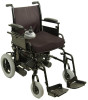
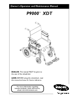
Owner's Operator and Maintenance Manual P9000™ XDT DEALER: This manual MUST be given to the user of the wheelchair. USER: BEFORE using this wheelchair, read this manual and save for future reference. For more information regarding Invacare products, parts, and services, please visit www.invacare.com - Invacare P9000XDT1818 | Owners Manual - Page 2
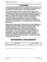
UNABLE TO UNDERSTAND THE WARNINGS, CAUTIONS AND INSTRUCTIONS, CONTACT INVACARE TECHNICAL SUPPORT BEFORE ATTEMPTING TO SERVICE OR OPERATE THIS EQUIPMENT - OTHERWISE, INJURY OR DAMAGE MAY RESULT. REFERENCE DOCUMENTS DOCUMENT MK5™NX™Electronics Manual PART NUMBER 1110532 NOTE: Updated versions of - Invacare P9000XDT1818 | Owners Manual - Page 3
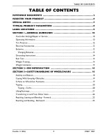
or Service 10 Operating Information...10 Tire Pressure ...12 Electrical Accessories ...12 Batteries...12 Charging Batteries ...13 Grounding Instructions ...14 Rain Test...14 Weight Training ...14 Weight Limitation...15 SECTION 2-EMI INFORMATION 16 SECTION 3-SAFETY/HANDLING OF WHEELCHAIRS 18 - Invacare P9000XDT1818 | Owners Manual - Page 4
25 Troubleshooting - Mechanical ...26 Troubleshooting Guide ...26 Checking Battery Charge Level...27 SECTION 5-WHEELCHAIR ...28 Joystick...28 Information Gauge Display ...29 Operating the Wheelchair...31 Turning the Power On/Off ...31 Using the Horn ...31 Using the ™ XDT 4 Part No. 1118386 - Invacare P9000XDT1818 | Owners Manual - Page 5
Installing/Removing/Adjusting Anti-Tippers 63 Installing...63 Removing ...63 Adjusting Height...63 SECTION 15-TRANSPORTING 65 Transporting the P9000 XDT...65 Unfolding/Folding the Wheelchair 65 Unfolding ...65 Folding ...65 LIMITED WARRANTY 68 Part No. 1118386 5 P9000™ XDT - Invacare P9000XDT1818 | Owners Manual - Page 6
ONLINE at warranty.invacare.com Please have your model number and purchase date available to complete your registration. Any registration information you submit will only be used by Invacare Corporation and protected as required by applicable laws and regulations. P9000™ XDT 6 Part No. 1118386 - Invacare P9000XDT1818 | Owners Manual - Page 7
this manual and apply . WHEELCHAIR USER As a manufacturer of wheelchairs, Invacare endeavors to supply a wide variety of wheelchairs to wheelchair, in a moving vehicle of any type. It is Invacare's position that users of wheelchairs should be replaced immediately. Wheelchairs that are used by - Invacare P9000XDT1818 | Owners Manual - Page 8
-TIPPERS FOOTRESTS/ LEGRESTS ARMRESTS UPHOLSTERY BATTERIES BATTERY/SIZE (NOT SUPPLIED) TWO REQUIRED SPEED (M.P.H.) TURNING RADIUS CHAIR ONLY CHAIR WITH battery discharge indicator on the joystick to determine the range of their wheelchair. Refer to When to Charge Batteries on page 66 for more - Invacare P9000XDT1818 | Owners Manual - Page 9
wheelchair have been pre-set at the factory to comply with the Veterans Administration functional Standard 8320.01 of the Federal Register, paragraph 3.2.4.5.3. If these wheel locks do not meet your needs, follow instructions on pneumatic tires). INSTRUCTIONS FOR WHEEL LOCK Owner's Manual for proper - Invacare P9000XDT1818 | Owners Manual - Page 10
instructions and any additional instructional material such as Owner's Manuals, Service Manuals or Instruction Sheets supplied wheelchair. Damage to the equipment could occur if improperly set-up or adjusted. Wheelchairs Wheelchairs wheelchair to tip over. DO NOT as the wheelchair may tip - Invacare P9000XDT1818 | Owners Manual - Page 11
motor release levers until the power is in the off position. Invacare strongly recommends proceeding down ramps or slopes at half speed or slower and to avoid hard braking or sudden stops. DO NOT attempt to lift the wheelchair by lifting on any removable (detachable) parts. Lifting by means of any - Invacare P9000XDT1818 | Owners Manual - Page 12
. Contact your oxygen supplier for instruction in the use of oxygen. Batteries The warranty and performance specifications contained in this manual are based on the use of deep cycle gel cell or sealed lead acid batteries. Invacare strongly recommends their use as the power source for this unit. If - Invacare P9000XDT1818 | Owners Manual - Page 13
to recharge the batteries and operate the wheelchair at the same time. DO NOT operate wheelchair with extension cord attached to the AC the manufacturer's instructions for each charger (supplied or purchased). If charging instructions are not supplied, consult a Part No. 1118386 13 P9000™ XDT - Invacare P9000XDT1818 | Owners Manual - Page 14
Instructions DO NOT, under any circumstances, cut or remove the round grounding prong from any plug used with or for Invacare products addition, Invacare has placed RED/ORANGE warning tags on some equipment. DO NOT remove these tags. Rain Test Invacare has tested its power wheelchairs in accordance - Invacare P9000XDT1818 | Owners Manual - Page 15
, the activity level of the individual wheelchair user is important. For instance, a 170 lb. active wheelchair could subject the wheelchair to more stress than a 250 lb. user. Invacare recommends that very active users consider the use of heavy-duty wheelchairs. Part No. 1118386 15 P9000™ XDT - Invacare P9000XDT1818 | Owners Manual - Page 16
POWERED WHEELCHAIR. Electromagnetic Interference (EMI) From Radio Wave Sources Powered wheelchairs and motorized scooters (in this text, both will be referred to as powered wheelchairs far as we know, are not likely to cause EMI problems to your powered wheelchair. P9000™ XDT 16 Part No. 1118386 - Invacare P9000XDT1818 | Owners Manual - Page 17
powered wheelchairs and motorized scooters. FOLLOWING THE WARNINGS LISTED BELOW SHOULD REDUCE THE CHANCE OF UNINTENDED BRAKE RELEASE OR POWERED WHEELCHAIR electronics of this wheelchair as manufactured by Invacare may adversely affect the EMI immunity levels. Part No. 1118386 17 P9000™ XDT - Invacare P9000XDT1818 | Owners Manual - Page 18
only as a "basic" guide. The techniques that are discussed on the following pages have been used successfully by many. Individual wheelchair users often develop skills to deal with daily living activities that may differ from those described in this manual. Invacare recognizes and encourages each - Invacare P9000XDT1818 | Owners Manual - Page 19
or traversing curbs or other impediments. Also, be aware of detachable parts such as arms or legrests. These must NEVER be used to move the wheelchair or as lifting supports, as they may be inadvertently released, resulting in possible injury to the user and/or assistant(s). When learning a new - Invacare P9000XDT1818 | Owners Manual - Page 20
. The second assistant should be positioned at the front of the wheelchair lifting upward on a non-removable (non-detachable) part of the wheelchair frame when lifting the wheelchair and stabilizing the wheelchair when the wheelchair is being lowered to the ground. The first assistant should turn - Invacare P9000XDT1818 | Owners Manual - Page 21
when it is necessary to move an unoccupied power wheelchair up or down the stairs. Invacare recommends using two assistants and making thorough preparations. Use ONLY secure, nondetachable parts for hand-hold supports. It is strongly recommended to lift the wheelchair only by the rear frame and the - Invacare P9000XDT1818 | Owners Manual - Page 22
Other Seats ƽ WARNING ALWAYS turn the wheelchair power OFF and engage the clutches to prevent the wheels from moving BEFORE attempting to transfer in or out of the wheelchair. Also make sure every precaution is taken the floor by reaching down between your knees. P9000™ XDT 22 Part No. 1118386 - Invacare P9000XDT1818 | Owners Manual - Page 23
to determine individual safety limits. Invacare strongly recommends ordering the wheel locks as an additional safeguard for the wheelchair user. FIGURE 3.2 Reaching, will extend without changing your sitting position. Part No. 1118386 FIGURE 3.3 Reaching and Bending Backward 23 P9000™ XDT - Invacare P9000XDT1818 | Owners Manual - Page 24
SECTION 4-SAFETY INSPECTION/TROUBLESHOOTING NOTE: Every six months or as necessary take your wheelchair to a qualified dealer for a thorough inspection and servicing. Regular cleaning will reveal loose or worn parts and enhance the smooth operation of your wheelchair. To operate properly - Invacare P9000XDT1818 | Owners Manual - Page 25
TROUBLESHOOTING ❑ Inspect tires for flat spots and wear. If tires are pneumatic, check for proper inflation. ❑ Ensure seat and/or back upholstery have no rips and do not sag. Replace if necessary. Inspect/Adjust Weekly ❑ Ensure seat is secured to wheelchair . Part No. 1118386 25 P9000™ XDT - Invacare P9000XDT1818 | Owners Manual - Page 26
for service. Check batteries for shorted cell. Replace if necessary. Contact dealer/Invacare. Poor connections between charger and wheelchair. Contact dealer/Invacare for service. Have charger checked. Replace batteries if necessary. Contact dealer/Invacare for service. Contact dealer/Invacare. Part - Invacare P9000XDT1818 | Owners Manual - Page 27
dealer/Invacare for service. Reprogram controller. Contact dealer/Invacare for service. Clean terminals. Contact dealer/Invacare. NOTE: For additional troubleshooting information and explanation of error codes, refer to the Electronics Manual (P/N 1110532) supplied with each wheelchair. Checking - Invacare P9000XDT1818 | Owners Manual - Page 28
the wheelchair moves. Your top speed, however, is limited by the setting of the speed-control knob and programmed settings. To slow the wheelchair to a stop, simply release the joystick. The wheelchair has automatic speed and direction compensation to minimize corrections. P9000™ XDT 28 Part No - Invacare P9000XDT1818 | Owners Manual - Page 29
joystick housing. It provides the following information to the user on the status of the wheelchair - 1. Power is on. 2. True state-of-battery-charge, including notification of when the battery following table of the diagnostic indications of the wheelchair status. Part No. 1118386 29 P9000™ XDT - Invacare P9000XDT1818 | Owners Manual - Page 30
SECTION 5-WHEELCHAIR OPERATION DISPLAY DESCRIPTION All LEDs are off. DEFINITION Power is Off. COMMENTS All LEDs are on. Power is On. Fewer . All LEDs are flashing slowly. Joystick has detected Out-of-Neutral-at-Power-Up mode. Release the joystick back to Neutral. All LEDs are flashing - Invacare P9000XDT1818 | Owners Manual - Page 31
the full potential of the proportional control and allow you to start and stop smoothly. To drive the wheelchair, perform the following: 1. Adjust speed control switch to the appropriate setting. 2. Turn the power on. Refer to Turning the Power On/Off on page 31. Part No. 1118386 31 P9000™ XDT - Invacare P9000XDT1818 | Owners Manual - Page 32
Pull back on the joystick. Move the joystick RIGHT. Move the joystick LEFT. Release the joystick and the wheelchair will quickly slow down. NOTE: The joystick MUST be in the NEUTRAL position for an accurate reading of FIGURE 5.2 Using the Joystick to Drive the Chair P9000™ XDT 32 Part No. 1118386 - Invacare P9000XDT1818 | Owners Manual - Page 33
, repair or service and BEFORE use, make sure that all attaching hardware is tightened securely - otherwise injury or damage may result. While the wheelchair is moving, the swingaway footrest assembly towards the inside of the wheelchair until it locks into place. Part No. 1118386 33 P9000™ XDT - Invacare P9000XDT1818 | Owners Manual - Page 34
footplate will be on the inside of the wheelchair when locked in place. Adjusting the Footrest Height protrude from holes on both sides of the upper footrest support. 6. Rotate cam lock lever down to locked position. Lock Lever Upper Footrest Support Release Button Lower Footrest Assembly P9000™ - Invacare P9000XDT1818 | Owners Manual - Page 35
buttons fully protrude from holes on both sides of the upper footrest support. 9. Rotate cam lock lever down to locked position. Mounting Screw Otherwise injury may occur due to pinch points. The wheelchair user's leg MUST be supported by an assistant before attempting to lower legrest. NOTE - Invacare P9000XDT1818 | Owners Manual - Page 36
FRONT RIGGINGS 1. To raise the elevating legrest, the assistant should hold the support tube and raise elevating legrests until the desired height is obtained. 2. To lower the elevating legrest, perform the following: A. Support user leg with one hand. B. Push release lever downward with other hand - Invacare P9000XDT1818 | Owners Manual - Page 37
may result. Before performing any maintenance, adjustment or service verify that on/off switch on the joystick is height adjustment lever is in the locked position before using the wheelchair. NOTE: For this procedure, refer to FIGURE 7.1. 1. Unlock Armrest Height Part No. 1118386 37 P9000™ XDT - Invacare P9000XDT1818 | Owners Manual - Page 38
4. Lock the swing-back arms by rotating the armrest release lever towards the inside of the wheelchair. Swing Back Arm Front Armrest Release Lever Rear Arm Socket FIGURE 7.2 Swing-Back Arms Replacing Assembly Mounting Screws FIGURE 7.3 Replacing Armrest Pad P9000™ XDT 38 Part No. 1118386 - Invacare P9000XDT1818 | Owners Manual - Page 39
. Before performing any maintenance, adjustment or service verify that on/off switch on the screws that secure the existing seat upholstery to the wheelchair frame. NOTE: Refer to the following table to existing seat upholstery from the wheelchair frame. 3. Install new seat upholstery by reversing - Invacare P9000XDT1818 | Owners Manual - Page 40
upholstery to the back canes. 3. Cut the tie wraps that secure the existing back upholstery to the wheelchair frame. 4. Securely tighten the new back upholstery to the back canes with the six mounting screws Mounting Screws FIGURE 8.2 Replacing the Back Upholstery P9000™ XDT 40 Part No. 1118386 - Invacare P9000XDT1818 | Owners Manual - Page 41
. Back Cane Mounting Screw Wheelchair Frame Locknut Back Height (in inches) *HOLE# 1 2 3 HEIGHT 17 18 19 *NOTE: Holes numbered from bottom to top for reference only. (There are no numbers on the back canes or wheelchair frame.) FIGURE 8.3 Adjusting the Back Height Part No. 1118386 41 - Invacare P9000XDT1818 | Owners Manual - Page 42
the seat cushion onto the seat upholstery. Washer Rear Phillips Screw Seat Upholstery Seat Positioning Strap Crossbrace FIGURE 8.4 Replacing Seat Positioning Strap P9000™ XDT 42 Part No. 1118386 - Invacare P9000XDT1818 | Owners Manual - Page 43
or damage may result. Before performing any maintenance, adjustment or service verify that On/Off switch on the joystick is in the on the right side of the wheelchair. To reposition the joystick onto the left side of the wheelchair, refer to Repositioning the Joystick Part No. 1118386 43 P9000™ XDT - Invacare P9000XDT1818 | Owners Manual - Page 44
securing the joystick control cord to the wheelchair. Before snipping the tie-wraps, note the 2. Remove the joystick from the wheelchair. 3. Remove the three hex wheelchair were snipped at the beginning of this procedure, re-secure the cord to the wheelchair operation of the wheelchair. Hex Mounting - Invacare P9000XDT1818 | Owners Manual - Page 45
Before performing any maintenance, adjustment or service verify that ON/OFF switch on boxes and battery tray from wheelchair. Refer to Removing/Installing the page 50. B. Tip back the wheelchair to floor. C. Pivot both forks of caster swing. 3. Test wheelchair for maneuverability. Dust Cover - Invacare P9000XDT1818 | Owners Manual - Page 46
hardware is tightened securely - otherwise injury or damage may result. Before performing any maintenance, adjustment or service verify that on/off switch on the joystick is in the off position. When to Charge Batteries Gauge FIGURE 11.1 When to Charge Batteries P9000™ XDT 46 Part No. 1118386 - Invacare P9000XDT1818 | Owners Manual - Page 47
NOTE: If charging instructions are not supplied, consult a qualified service technician for proper procedures. Required items: TOOLS Battery charger *Extension cord QUANTITY 1 1 COMMENTS Supplied Not Supplied *NOTE: 3-prong plug, 15 ampere current rating; industrial type Part No. 1118386 47 - Invacare P9000XDT1818 | Owners Manual - Page 48
specifications contained in this manual are based on the use of deep cycle gel cell or sealed lead acid batteries. Invacare strongly recommends their use as the power source for this unit. CAUTION Failure to use the correct battery size and/or voltage may cause damage to your wheelchair and give you - Invacare P9000XDT1818 | Owners Manual - Page 49
to FIGURE 11.3 on page 50. NOTE: To remove the battery boxes from the wheelchair, reverse the following procedure. 1. Verify that the on/off switch on the joystick is to Electronics Manual (P/N 1110532). 3. Slide front battery box toward the front of the wheelchair. Part No. 1118386 49 P9000™ XDT - Invacare P9000XDT1818 | Owners Manual - Page 50
boxes in place before using the wheelchair. 6. Connect the battery box retaining To remove the battery tray from the wheelchair, reverse the following procedure. 1. Attach the wheelchair. 2. Attach the hanger brackets to the wheelchair frame. Hanger Bracket Key Slot Bracket Battery Tray Wheelchair - Invacare P9000XDT1818 | Owners Manual - Page 51
power to the wheelchair is OFF before performing this procedure. The use of rubber gloves and chemical goggles or face shields is recommended when working with batteries. Invacare life of the battery. The battery lifting strap supplied is for Group 22NF batteries ONLY. Refer to the battery - Invacare P9000XDT1818 | Owners Manual - Page 52
1. If necessary, remove the battery boxes from the wheelchair. Refer to Removing/Installing the Battery Boxes on page or Hold Down Flanges U1 Battery Box Bottom Battery Battery Group 22NF ONLY Terminal(s)/Post(s) 22NF Battery Box, Bottom FIGURE 11 may occur. P9000™ XDT 52 Part No. 1118386 - Invacare P9000XDT1818 | Owners Manual - Page 53
Clamp DO NOT USE Group 22NF Batteries POSITIVE (+) Terminal . Refer to FIGURE 11.7. • Dual Group 22NF Batteries with Mounting Holes in the Refer to FIGURE 11.7. • Dual Group 22NF Batteries without Mounting Holes in the onto BLACK battery cable. B. Dual Group 22NF BATTERIES i. RED battery terminal - Invacare P9000XDT1818 | Owners Manual - Page 54
: It will be necessary to trim excess tie-wrap in order to install the battery box top(s). 7. Install the battery box top(s). P9000™ XDT 54 Part No. 1118386 - Invacare P9000XDT1818 | Owners Manual - Page 55
Black Cable NEGATIVE (-) Terminal/Post CONNECT CABLE TO TERMINAL AS SHOWN. Detail "B" - Dual Group 22 NF Batteries 1/4-20 x 7/8-Inch Hex Flange Screw NEGATIVE (-) Terminal/Post POSITIVE (+) manner. FIGURE 11.7 Connecting Battery Cables - Direct Mount Method Part No. 1118386 55 P9000™ XDT - Invacare P9000XDT1818 | Owners Manual - Page 56
SECTION 11-BATTERIES 8. Install the battery box(es) into the wheelchair. Refer to Removing/Installing the Battery Boxes on page 49. NOTE: New battery(ies) MUST be fully the POSITIVE (+) battery terminal/post is positioned as shown in FIGURE 11.8, proceed to STEP 2. P9000™ XDT 56 Part No. 1118386 - Invacare P9000XDT1818 | Owners Manual - Page 57
the battery box top(s). 8. Install the battery box top(s). 9. Install the battery box(es) into the wheelchair. Refer to Removing/Installing the Battery Boxes on page 49. NOTE: New battery(ies) MUST be fully the battery(ies). Refer to Charging Batteries on page 47. Part No. 1118386 57 P9000™ XDT - Invacare P9000XDT1818 | Owners Manual - Page 58
- Tie-Wraps NEGATIVE (-) Terminal/Post POSITIVE (+) Terminal/Post Tie-Wraps RED Clamp Cover Group 22NF Battery BLACK Clamp Cover Detail "C" - Installing Battery Clamp Cover Clamp Cover Cable NOTE: 11.9 Connecting Battery Cables - Battery Clamp Method P9000™ XDT 58 Part No. 1118386 - Invacare P9000XDT1818 | Owners Manual - Page 59
50. 7. Reinstall the battery boxes from the wheelchair. Refer to Removing/Installing the Battery Boxes on page 49. Adjustable End Retaining Strap Buckle Retaining Strap Battery Tray Slots Retaining Strap Battery Tray Slots Retaining Strap Part No. 1118386 FIGURE 11.10 Replacing Battery Box - Invacare P9000XDT1818 | Owners Manual - Page 60
adjustments, repair or service and BEFORE use, the clutches until the power is off. NOTE maneuver the wheelchair without power. To engage the wheelchair. NEVER try to turn the clutch handles towards the front of the wheelchair. • of the wheelchair. Top View Of Wheelchair Disengaged (Toward rear - Invacare P9000XDT1818 | Owners Manual - Page 61
LOCKS ƽ WARNING After ANY adjustments, repair or service and BEFORE use, make sure all attaching hardware wheelchair. 10. Repeat STEPS 3-9 until the wheel locks engage the rear wheels enough to hold the wheelchair. 11. Engage clutches. Refer to Engaging/Disengaging the Clutches on page 60. Part - Invacare P9000XDT1818 | Owners Manual - Page 62
Handle FIGURE 13.1 Installing/Adjusting/Using the Wheel Locks Using The wheelchair is equipped with a pair of independently operated wheel locks located just use the wheel locks when the wheelchair power is on and the clutches are engaged - otherwise damage to the wheelchair may result. NOTE: Use - Invacare P9000XDT1818 | Owners Manual - Page 63
adjustments, repair or service and BEFORE use, protruding out of adjustment holes BEFORE using the wheelchair. Ensure both anti-tippers have the same ground buttons in and remove the anti-tippers from the support tubes. Adjusting Height 1. Press the release buttons in Part No. 1118386 63 P9000™ XDT - Invacare P9000XDT1818 | Owners Manual - Page 64
SECTION 14-ANTI-TIPPERS Wheelchair Frame Release Button Anti-tipper Release Button Anti-tipper Adjustment Holes 1½ to 2-inch Clearance FIGURE 14.1 Installing/Removing/Adjusting Anti-Tippers P9000™ XDT 64 Part No. 1118386 - Invacare P9000XDT1818 | Owners Manual - Page 65
power wheelchair. Invacare recommends using two assistants and making thorough preparations. Make sure to use ONLY secure, non-detachable parts for hand-hold supports are positioned in the seat guides. 2. Assemble the wheelchair by following the instructions in this manual. Folding 1. Remove the - Invacare P9000XDT1818 | Owners Manual - Page 66
Anti-Tippers on page 63. Refer to Installing/Removing/Using the Footrest/Legrest on page 33. FIGURE 15.1 Transporting the P9000 XDT P9000™ XDT 66 Part No. 1118386 - Invacare P9000XDT1818 | Owners Manual - Page 67
NOTES SECTION 15-TRANSPORTING Part No. 1118386 67 P9000™ XDT - Invacare P9000XDT1818 | Owners Manual - Page 68
INVACARE. THE WARRANTY SHALL NOT APPLY TO PROBLEMS ARISING FROM NORMAL WEAR AND TEAR OR FAILURE TO ADHERE TO THE PRODUCT INSTRUCTIONS licensed to Invacare Corporation unless otherwise noted. Phillips is a registered trademark of the Phillips Screw Company. © 2007 Invacare Corporation Part No.
-
 1
1 -
 2
2 -
 3
3 -
 4
4 -
 5
5 -
 6
6 -
 7
7 -
8
-
9
-
10
-
11
-
12
-
13
-
14
-
15
-
16
-
17
-
18
-
19
-
20
-
21
-
22
-
23
-
24
-
25
-
26
-
27
-
28
-
29
-
30
-
31
-
32
-
33
-
34
-
35
-
36
-
37
-
38
-
39
-
40
-
41
-
42
-
43
-
44
-
45
-
46
-
47
-
48
-
49
-
50
-
51
-
52
-
53
-
54
-
55
-
56
-
57
-
58
-
59
-
60
-
61
-
62
-
63
-
64
-
65
-
66
-
67
-
68
 |
 |
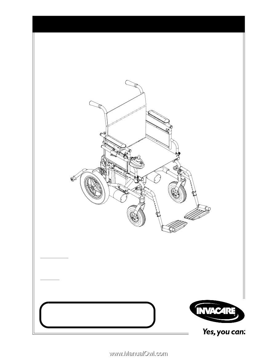
Owner’s Operator and Maintenance Manual
DEALER:
This manual MUST be given to
the user of the wheelchair.
USER:
BEFORE using this wheelchair, read
this manual and save for future reference.
For more information regarding
Invacare products,
parts, and services,
please visit www.invacare.com
P9000
™
XDT