Invacare P9000XDT1818 Owners Manual - Page 61
Wheel Locks
 |
View all Invacare P9000XDT1818 manuals
Add to My Manuals
Save this manual to your list of manuals |
Page 61 highlights
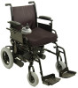
SECTION 13-WHEEL LOCKS SECTION 13-WHEEL LOCKS ƽ WARNING After ANY adjustments, repair or service and BEFORE use, make sure all attaching hardware is tightened securely - otherwise injury or damage may result. Installing/Adjusting/Using the Wheel Locks NOTE: For this procedure, refer to FIGURE 13.1 on page 62. Installing/Adjusting NOTE: Before adjusting or replacing the wheel lock assemblies, ensure that the tires are inflated to the recommended psi on the side wall of tire. NOTE: If necessary, remove threaded plastic insert from the wheel lock mounting hole in the wheelchair frame. 1. Position the wheel lock on the wheelchair frame. 2. Loosely install the hex screw and locknut that secures the wheel lock to the wheelchair frame. 3. Make sure wheel lock is disengaged from rear wheel. 4. Measure the distance between the wheel lock shoe and the rear wheel. 5. Slide the wheel lock along the wheelchair until the measurement is between 5/32 and 5/16-inches. 6. Tighten the wheel lock to the wheelchair frame. 7. Repeat STEPS 2-6 for the opposite wheel lock. 8. Disengage the clutches. Refer to Engaging/Disengaging the Clutches on page 60. 9. Engage the wheel locks and push against the wheelchair to determine if the wheel locks engage the rear wheels enough to hold the wheelchair. 10. Repeat STEPS 3-9 until the wheel locks engage the rear wheels enough to hold the wheelchair. 11. Engage clutches. Refer to Engaging/Disengaging the Clutches on page 60. Part No. 1118386 61 P9000™ XDT
-
 1
1 -
2
-
3
-
4
-
5
-
6
-
7
-
8
-
9
-
10
-
11
-
12
-
13
-
14
-
15
-
16
-
17
-
18
-
19
-
20
-
21
-
22
-
23
-
24
-
25
-
26
-
27
-
28
-
29
-
30
-
31
-
32
-
33
-
34
-
35
-
36
-
37
-
38
-
39
-
40
-
41
-
42
-
43
-
44
-
45
-
46
-
47
-
48
-
49
-
50
-
51
-
52
-
53
-
54
-
55
-
 56
56 -
 57
57 -
 58
58 -
 59
59 -
 60
60 -
 61
61 -
 62
62 -
 63
63 -
 64
64 -
 65
65 -
 66
66 -
67
-
68
 |
 |
