Invacare P9000XDT1818 Owners Manual - Page 9
Label Locations
 |
View all Invacare P9000XDT1818 manuals
Add to My Manuals
Save this manual to your list of manuals |
Page 9 highlights
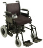
LABEL LOCATIONS LABEL LOCATIONS Crossmember Lower Frame Tube IMPORTANT NOTICE The wheel locks on this wheelchair have been pre-set at the factory to comply with the Veterans Administration functional Standard 8320.01 of the Federal Register, paragraph 3.2.4.5.3. If these wheel locks do not meet your needs, follow instructions below. ! CAUTION Any wheel lock adjustments should embed wheel lock shoe at least 1/8" into tire when locked (3/16" on pneumatic tires). INSTRUCTIONS FOR WHEEL LOCK ADJUSTMENTS 1. Loosen wheel lock mounting fastener, which runs through mounting bracket and frame. 2. Slide clamp toward rear wheel until wheel lock shoe is embedded into tire material at least 1/8" when handle is engaged to the lock position (3/16" for pneumatic tires). 3. Tighten mounting fastener to secure mounting bracket in desired location and recheck lock shoe embedding. 4. Inspect for correct locking action BEFORE actual use. 00078X021-0394 Serial Number Label Location WARNING Refer to Owner's Manual for proper anti-tipper setting. 1085379 WARNING DO NOT OPERATE WITHOUT THE ANTI-TIP TUBES REV. 5/98 INSTALLED. P/N 60106X144 Part No. 1118386 9 P9000™ XDT
-
 1
1 -
2
-
3
-
 4
4 -
 5
5 -
 6
6 -
 7
7 -
 8
8 -
 9
9 -
 10
10 -
 11
11 -
 12
12 -
 13
13 -
 14
14 -
15
-
16
-
17
-
18
-
19
-
20
-
21
-
22
-
23
-
24
-
25
-
26
-
27
-
28
-
29
-
30
-
31
-
32
-
33
-
34
-
35
-
36
-
37
-
38
-
39
-
40
-
41
-
42
-
43
-
44
-
45
-
46
-
47
-
48
-
49
-
50
-
51
-
52
-
53
-
54
-
55
-
56
-
57
-
58
-
59
-
60
-
61
-
62
-
63
-
64
-
65
-
66
-
67
-
68
 |
 |
