JVC GYHD110U Instructions
JVC GYHD110U - Camcorder - 720p Manual
 |
UPC - 046838027345
View all JVC GYHD110U manuals
Add to My Manuals
Save this manual to your list of manuals |
JVC GYHD110U manual content summary:
- JVC GYHD110U | Instructions - Page 1
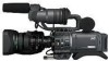
: Enter below the Serial No. which is located on the body. Retain this information for future reference. Model No. Serial No. * The illustration shows the GY-HD110/GYHD111 HD CAMERA RECORDER with the provided lens, viewfinder, microphone and battery pack attached. LST0392- - JVC GYHD110U | Instructions - Page 2
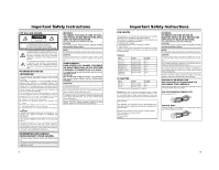
Install in accordance with the manufacturer's instructions. 8. Do not install near any attachments/accessories specified by the manufacturer. 12. Use only with the cart, stand, tripod, bracket of time. 14. Refer all servicing to qualified service personnel. Servicing is required when the apparatus - JVC GYHD110U | Instructions - Page 3
and light industry; e.g. offices or theatres z urban outdoors In order to keep the best performance and furthermore for electromagnetic compatibility we recommend to use cables not exceeding the following length: Camera Port DC INPUT INPUT1/2 LINE OUTPUT PHONES 1/2 VIDEO/Y, PB, PR IEEE1394 (HDV/DV - JVC GYHD110U | Instructions - Page 4
the GY-HD110U/GYHD111E.) ACCESSORIES (Excluding the CHU/CHE model) Lens Microphone / This unit is a HDV/DV video system format camera recorder. Videocassettes marked with the A symbol can be used. The following phenomena may occur when tapes recorded on other units (including another GY-HD110 - JVC GYHD110U | Instructions - Page 5
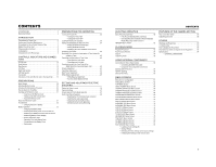
Dubbing with AV Devices 57 HDV/DV Dubbing 58 Backup Recording 60 MENU SCREENS Menu Screen Configuration 61 Setting Menu Screens 62 TOP MENU Screen 63 VIDEO FORMAT Menu Screen 64 CAMERA OPERATION Menu Screen 66 CAMERA PROCESS [1/2] Menu Screen 67 CAMERA PROCESS [2/2] Menu Screen 68 ADVANCED - JVC GYHD110U | Instructions - Page 6
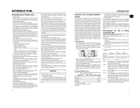
cause damage or a fire. • When carrying the camera, be sure to hold the carrying handle. Holding the lens or viewfinder may result in damage. 6 INTRODUCTION Routine and Periodical Mainte- nance The GY-HD110 incorporates precision mechanical parts, which will collect dirt, wear out and deteriorate - JVC GYHD110U | Instructions - Page 7
Pack to be Used The GY-HD110 can use any of the following batteries. • BN-V428, BN-V438 Videocassette to be Used • Use JVC's videocassette tapes marked with the A symbol. • Mini DV videocassette : M-DV63HD M-DV63PROHD * Do not use M-DV80. • Videocassettes cannot be used upside down. • Avoid storing - JVC GYHD110U | Instructions - Page 8
sold microphone. X See "Attaching the Microphone (Provided)" on page 30. 4Front tally lamp This lamp lights up when the GY-HD110 enters the record mode. It blinks during the transition to the record mode. When the tape has run out, or the VTR enters the warning mode, it blinks quickly. • Use the - JVC GYHD110U | Instructions - Page 9
hole Use this to prevent the camera from falling off the tripod. Always make sure that the camera is securely mounted. 6 5 1Back tally lamp This lamp lights up when the GY-HD110 enters the record mode. It blinks during the transition to the record mode. When the tape has run out, or the VTR - JVC GYHD110U | Instructions - Page 10
do not work.) h[HDV/DV LED] • In camera mode, this lights according to the setting for the video format being shot. • In VTR mode, it lights according to the video format being recorded on tape or the IEEE1394 input video format. HDV : Lights when the format is HDV. DV : Lights when the format is - JVC GYHD110U | Instructions - Page 11
in the VTR mode. (GY-HD110U/GY-HD111E only) MEMO Alarm sound is not output. 3[IEEE1394] IEEE1394 switch Input/output signal and playback signal video from the IEEE1394 connector 4. Set this switch according to the format. HDV : For HDV format DV : DV format 4[IEEE1394] IEEE1394 connector (6-pin - JVC GYHD110U | Instructions - Page 12
lights when the camera is in the VTR mode. To perform VTR playback or to input the HDV/DV signal from the IEEE1394 connector 4 on page 16, press the CAM/VTR button 5 on page13 to turn on this indicator. It flashes when the mode is being changed. (HDV/DV signal input is possible with the GY-HD110U - JVC GYHD110U | Instructions - Page 13
Viewfinder (Cont'd) „ Status Screens in the Camera Mode 1 0 266S DD 9 8 7 6 5 4 2 3 STATUS 0 Screen • STATUS 0 1 Event Indication When the Gain or Shutter Speed is changed manually, the setting was sent from the IEEE1394 TRIGGER TO HDV, TRIGGER TO DV connector Other Displays X See "FILE - JVC GYHD110U | Instructions - Page 14
tape indication is to be regarded only as a guide. * When the unit is used at low temperatures, it may take a while before the indication of the remaining tape time appears. (Example) 7.0V: Indicates remaining battery /MIC [1/2] menu screen is set to 48 K. (Au- dio is recorded with 16-bit, 48 kHz - JVC GYHD110U | Instructions - Page 15
, and rewind. During recording in DV format, the data from the IEEE1394 connector is displayed. During recording in HDV format, the data of internal clock is displayed. (GY-HD110U/GY-HD111E only) Whether or not the date and time should be displayed and the display style are set on the TIME/DATE - JVC GYHD110U | Instructions - Page 16
GY-HD110 with the Anton-Bauer or IDX battery). Only image displayed Characters shown enlarged Image and characters displayed No. Item Contents 1 Audio Lock Indicator Displayed during recording and playback when the audio signal is locked to the video signal. 2 Time Code Generator Setting - JVC GYHD110U | Instructions - Page 17
ACM-12 CARRYING CASE TRIPOD BASE KA-551 TRIPOD IEEE1394 CABLE 6P-6P Battery Battery Charger IDX Anton Bauer HDD UNIT DR-HD100 DV VTR BR-HD50 Non-linear Editing SYSTEM DOLLY *1 An HZ-FM13 cannot be used with a Th16×5.5BRMU or S14×7.3B12/U zoom lens. Use a FUJINON focus manual unit (FMM-8, CFH - JVC GYHD110U | Instructions - Page 18
in the direction of the arrow as you slide the viewfinder. Inserting an SD Memory Card Cutout SD memory card cover LOCK switch PREPARATIONS By using an SD memory card, you can save and call up menu settings and camera settings for this camcorder. X See "FILE MANAGE Menu Screen" on page 83. Check - JVC GYHD110U | Instructions - Page 19
code data are reset. In this case, recharge the built-in battery and then set the date and time and time code data again. However, it is possible to use the GY-HD110 even if the builtin battery is discharged but the date and time and time code data cannot be recorded. „ How to charge 1. Connect the - JVC GYHD110U | Instructions - Page 20
area of the LCD monitor or in the viewfinder. HDV/DV input is possible through the IEEE1394 connector. (GY-HD110U/GY-HD111E only) „ Turning the Power OFF 1. Place the GY-HD110 in the record-standby or STOP mode. 2. Set the POWER switch to OFF. 3. Remove the battery pack or the power supply to the - JVC GYHD110U | Instructions - Page 21
the built-in backup battery the set date and time data continue to count even when the power is switched off. • The set date and time data are displayed on the LCD mon- itor or in the viewfinder and recorded on the tape in accordance with the settings made on the menu screen. „ Setting the Date and - JVC GYHD110U | Instructions - Page 22
tape are displayed. In VTR stop mode : The last read date and time values are displayed. When an HDV/DV sig- : The date and time of the DV input nal is input from the are displayed in DV format. The IEEE1394 connector date and time of the internal clock are displayed in HDV format. (GY- HD110U - JVC GYHD110U | Instructions - Page 23
Time Codes in Continuation of Time Codes Recorded on Tape The GY-HD110 also incorporates a time code reader. Therefore, when the unit enters record mode from record-standby mode, it can read the time code data recorded on the tape and record time codes in continuation of the existing data. The - JVC GYHD110U | Instructions - Page 24
GY-HD100U/GY-HD100E/GY-HD101E/GY-HD110U/GY-HD110E/GY-HD111E) 1. Set the IEEE1394 switch on the left side to [DV]. 2. Set to Camera mode. 3. Set the recording format to DV-60I or DV50I. 4. Set the TC GENE. switch to [FREE]. • Slave unit (GY-HD110U/GY-HD111E) 1. Set from the lens side (vertically - JVC GYHD110U | Instructions - Page 25
condition changes. This mode is convenient when you have no time to adjust the white balance or when the camera is moved frequently in and out of places under different lighting conditions. „ Setting procedure The FAW function can be activated with the FAW item on the SWITCH MODE menu screen. The - JVC GYHD110U | Instructions - Page 26
. X See page 64. • To record using the standard screen, set ASPECT to 4:3. • To record using the 16:9 screen, set ASPECT to 16:9. 16:9 TV 16:9 4:3 TV [SQUEEZE] 4:3 TV [SIDE CUT] 4:3 TV [LETTER] 16:9 TV MEMO • When you set the REC item on the VIDEO FORMAT menu to HDV format, the ASPECT item is - JVC GYHD110U | Instructions - Page 27
level (reference) The GY-HD110 is provided with the tape end is reached or when the battery is running down. * Do not increase the audio monitoring volume excessively; otherwise howling with the camera microphone may occur. MEMO • When connecting a stereotype earphone, make the following settings - JVC GYHD110U | Instructions - Page 28
viewfinder or on the monitor connected to the video signal output connectors. 1. In the record-standby mode, press the RET button on the camera lens section. • The tape rewinds and about 6 seconds of the content recorded in DV format is played back, and about 8 seconds of the content recorded in HDV - JVC GYHD110U | Instructions - Page 29
time code following completion of HEADER REC recording will be in accordance with the setting of the TC GENE. switch. FREE RUN: Continuous running. REC RUN or REGEN: Runs only during REC. • Camera images are not output to the LCD monitor, viewfinder or video output during REW mode when the HEADER - JVC GYHD110U | Instructions - Page 30
is possible in the case of DV input. (GY-HD110U/GY-HD111E only)) When the GY-HD110 is used for playback of a tape that was recorded on another unit with audio recorded on the CH-3 and CH-4 channels, the PB AUDIO CH [DV] item on the AUDIO menu screen must be set. After-recording on the CH-3 and - JVC GYHD110U | Instructions - Page 31
the CAM/VTR button. The VTR indicator lights. 4. Set the video output. Set the VIDEO FORMAT menu screen. X See page 64. • HDV PB OUTPUT item: Set the video format to be output from the video output terminal during tape playback. • PB TAPE item: Select whether to automatically detect the playback - JVC GYHD110U | Instructions - Page 32
perform this type of operation, set the speaker volume as low as possible on the audio device connected to the camcorder. • Recording may not be possible in some cases even if the recorder is equipped with a IEEE1394 connector. 58 1. IEEE1394 switch IEEE 1394 HDV DV PR VIDEO/Y PR DC INPUT LINE - JVC GYHD110U | Instructions - Page 33
USING EXTERNAL COMPONENTS Backup Recording 1. IEEE1394 switch PB VIDEO/Y IEEE 1394 HDV DV PR DC INPUT LINE OUTPUT IEEE1394 Master unit GY-HD110 Backup unit Signal flow IEEE1394 cable CAUTION • Set the IEEE1394 switch on both devices to either HDV or DV. • Start recording after making sure - JVC GYHD110U | Instructions - Page 34
monitor or the viewfinder screen. If the OUTPUT CHAR. item on the OTHERS [1/2] screen is set to ON, the menu screen can also be viewed on a monitor connected to the video signal output connector. 1. Set the POWER switch to ON. 2. Set the mode of the GY-HD110 with the CAM/VTR button. (Camera mode or - JVC GYHD110U | Instructions - Page 35
camcorder is in VTR mode or is ejecting a tape. Sets the video format for shooting. (Can only be displayed and set in camera mode) You can set the following according to the FRAME RATE. Setting DV-60I HDV-SD60P HDV-HD30P HDV-SD50P HDV-HD25P DV-50I DV-25P DV-24P DV-24PA HDV-HD24P Description DV - JVC GYHD110U | Instructions - Page 36
contour compensation frequency for the contours (details). Compensates for distortion when outputting progressive video to an interlaced monitor. HIGH : Enhances high frequency bands. LOW : Enhances low frequency bands. Sets ON/OFF for the skin detail function. OFF : Turns off the skin - JVC GYHD110U | Instructions - Page 37
video smoother when the tape is played back by adding frames to the signal recorded on the tape during progressive shooting. OFF : Does not function. ON : Functions. MEMO This can be set when you select "HDV-HD30p", "HDV-HD25p", or "HDV CAMERA mode. • When the DNR is set to ON, the camcorder's - JVC GYHD110U | Instructions - Page 38
: Set when shooting a computer monitor, etc. You can set the following using the REC item on the VIDEO FORMAT menu screen. (This is fixed at EEI when in FULL AUTO mode) REC Item DV-60I HDV-SD60P HDV-HD30P DV-50I HDV-SD50P HDV-HD25P DV-25P DV-24P DV-24PA HDV-HD24P Setting for STEP Setting for - JVC GYHD110U | Instructions - Page 39
from the INPUT1 connector. INPUT2 : Only cuts the low frequencies in the audio from the INPUT2 connector. BOTH : Cuts the low frequencies in the audio from both the INPUT1 and INPUT2 terminals. Sets the reference audio level on the tape. (Both CH-1 and CH-2) -20dB : Records with -20 dB as the - JVC GYHD110U | Instructions - Page 40
in the VTR mode. Item VIDEO FORMAT TAPE REMAIN TC/UB AUDIO BATTERY INFO NEXT PAGE PAGE BACK Function/Setting (bold characters indicate initial settings) Selects whether to display the video format in the status display on the LCD monitor or the viewfinder. (Camera mode: STATUS 1 screen, VTR mode - JVC GYHD110U | Instructions - Page 41
bits (UB) during IEEE1394 input of HDV/DV format. OFF : Records the TC/UB set in the camcorder. ON : Records the TC/UB of the IEEE1394 input. MEMO In HDV format, the UB set in the camcorder is recorded regardless of the setting. HEADER REC To make settings related to the HEADER REC function - JVC GYHD110U | Instructions - Page 42
the status display on the LCD monitor or in the viewfinder. OFF : Not displayed. ON : Displayed. When a tape with time and date not recorded is played back, there will be no display of time and date even when this item is set to ON. In the Camera mode, the date and time are displayed in - JVC GYHD110U | Instructions - Page 43
* BACK SPACE [HDV]* Function/Setting (bold characters indicate initial settings) Sets how to control the REC trigger command output from the IEEE1394 connector. (Can be displayed and set in camera mode) Set this when recording a backup of the DV signal from this camcorder onto another device - JVC GYHD110U | Instructions - Page 44
The camera mode and VTR mode menu settings are reset. (The TC PRESET, UB PRESET, and CLOCK ADJUST settings are not reset.) CANCEL : The settings are not reset. EXECUTE : The settings are reset. MEMO • The cursor (K) does not move to this item when the camcorder is in VTR mode or is ejecting a tape - JVC GYHD110U | Instructions - Page 45
memory card. • NO ACCESS: There is a problem with the SD memory card. Replace the SD VIDEO FORMAT: A settings file for a video format that is not supported was called up. Settings files for video formats that are not supported card has been inserted into the camcorder. 1. Turn the SHUTTER dial, - JVC GYHD110U | Instructions - Page 46
CAMERA PROCESS [1/2] menu screen. In addition, you can use the LEVEL item to set three levels of suppression of skin color area detail enhancement in the video in color in the LCD monitor or viewfinder. MEMO When COLOR GAIN item on the ADVANCED PROCESS menu screen is set to "OFF", only the portion - JVC GYHD110U | Instructions - Page 47
TAPE! A computer data tape or a DVC PRO cassette was used. Use a MiniDV videocassette. LP TAPE INVALID!* Tried to play back a tape recorded in LP mode. This camcorder cannot record or play back in LP mode. NO DV SIGNAL* DV signal was not input. Set the IEEE1394 switch to DV and input a DV - JVC GYHD110U | Instructions - Page 48
Please consult the person in charge of professional video equipment at your nearest JVC-authorized service agent. 5605 - 5609 DEFECTIVE TAPE Tape is cut. Operation stops. Press the EJECT button to take out the cassette. If the tape runs out during recording, switch the power OFF and then switch - JVC GYHD110U | Instructions - Page 49
display "STOP". Cannot play back. • Is the PB TAPE item on the VIDEO FORMAT menu screen set to a setting other than AUTO? If this menu item and the tape format do not match, the tape cannot be played back. Cannot input an HDV/DV signal. • Is the camcorder in VTR mode? (Is the VTR indicator lit - JVC GYHD110U | Instructions - Page 50
Approx. 16.5 W (in the Record mode) : 235 (W) × 232 (H) × 341 (D) mm : 3.3 d (7.3 lbs.) (including lens (Th16×5.5BRMU), viewfinder, battery pack, microphone and tape) : 0°C to 40°C (32°F to 104°F) : -20°C to 60°C (-4F° to 140°F) : 30% to 80% RH : 85% RH or less [Camera section] Image pickup device - JVC GYHD110U | Instructions - Page 51
screen is displayed. Ⅵ The time code preset screen is displayed on the LCD screen or viewfinder. It will not be output from the VIDEO OUT terminal. 48.5 EXTERNAL DIMENSIONS (unit: mm) * Design and specifications are subject to change without notice © 2006 Victor Company of Japan, Limited LST0533-
-
 1
1 -
 2
2 -
 3
3 -
 4
4 -
 5
5 -
 6
6 -
 7
7 -
8
-
9
-
10
-
11
-
12
-
13
-
14
-
15
-
16
-
17
-
18
-
19
-
20
-
21
-
22
-
23
-
24
-
25
-
26
-
27
-
28
-
29
-
30
-
31
-
32
-
33
-
34
-
35
-
36
-
37
-
38
-
39
-
40
-
41
-
42
-
43
-
44
-
45
-
46
-
47
-
48
-
49
-
50
-
51
 |
 |
INTRODUCTION
CONTROLS,
INDICATORS AND
CONNECTORS
PREPARATIONS
PREPARATIONS
FOR OPERATION
SETTING AND
ADJUSTMENTS
BEFORE SHOOTING
SHOOTING
OPERATION
PLAYBACK MODE
USING EXTERNAL
COMPONENTS
MENU SCREENS
FEATURES OF THE
CAMERA SECTION
OTHERS
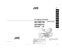
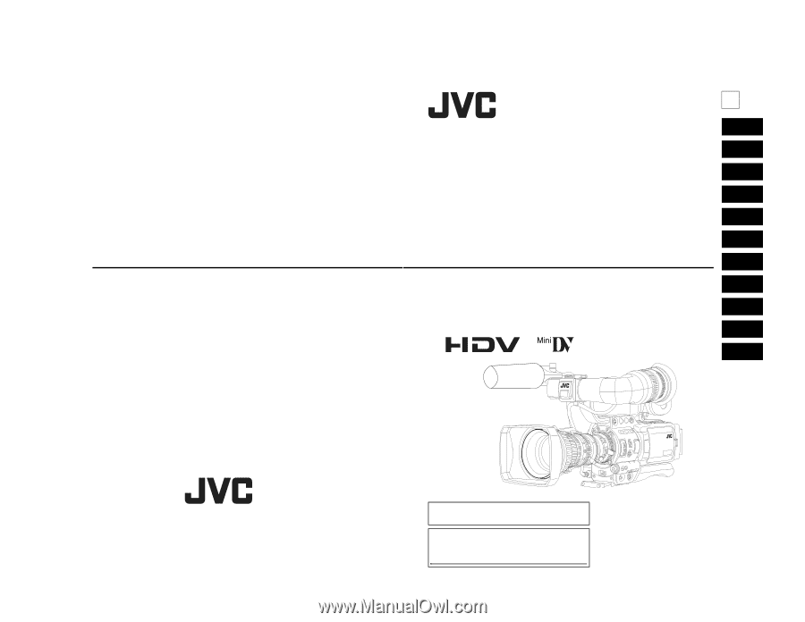
HD CAMERA RECORDER
INSTRUCTIONS
GY-HD110
GY-HD111
Thank you for purchasing this JVC product. Before operating this
unit, please read the instructions carefully to ensure the best
possible performance.
For Customer Use :
Enter below the Serial No. which is located on the body.
Retain this information for future reference.
Model No.
Serial No.
* The illustration shows the GY-HD110/GY-
HD111 HD CAMERA RECORDER with the pro-
vided lens, viewfinder, microphone and battery
pack attached.
LST0392-
E
LST0392-
© 2006 Victor Company of Japan, Limited