JVC GYHD110U Instructions - Page 13
Indications on the LCD Monitor and in the Viewfinder Cont'd - camera
 |
UPC - 046838027345
View all JVC GYHD110U manuals
Add to My Manuals
Save this manual to your list of manuals |
Page 13 highlights
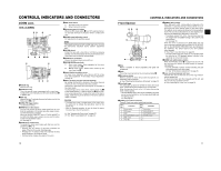
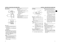
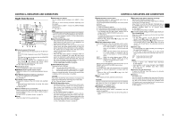
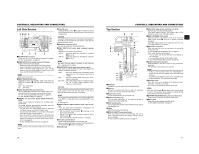
CONTROLS, INDICATORS AND CONNECTORS Indications on the LCD Monitor and in the Viewfinder (Cont'd) „ Status Screens in the Camera Mode 1 0 266S DD 9 8 7 6 5 4 2 3 STATUS 0 Screen • STATUS 0 1 Event Indication When the Gain or Shutter Speed is changed manually, the setting condition is displayed for about 3 seconds at the time the change is made. Setting Status Contents of Indications Gain value was changed GAIN 0 dB, 3 dB, 6 dB, 9 dB, 12 dB, 15 dB, 18 dB Gain value reached the ALC GAIN ALC FULL AUTO was turned ON/OFF FULL AUTO ON, FULL AUTO OFF ZEBRA was turned ON/OFF ZEBRA ON, ZEBRA OFF Shutter speed value was changed *1 SHUTTER 1/6, 1/6.25, 1/7.5, 1/12, 1/12.5, 1/15, 1/24, 1/25, 1/30, 1/48, 1/50, 1/60, 1/100, 1/120, 1/250, 1/500, 1/1000, 1/2000,1/4000, 1/10000 Variable shutter speed value was changed *1 V. SHUTTER 1/24.01 to 1/1998.0 Shutter was turned OFF SHUTTER OFF [1/**] *4 White balance value was changed (Example) WHITE BAL A Numeric value: Any of 2300, 2500, 2800, 3000, 3200, 3400, 3700, 4300, 5200, 5600, 6500, 8000 FILTER value was changed FILTER OFF, FILTER ND 1 [1/4ND], FILTER ND 2 [1/16ND] AE LEVEL value was changed *2 AE LEVEL -3, -2, -1, NORMAL, +1, +2, +3 BLACK gain value was changed *2 BLACK NORMAL BLACK STRETCH 1, 2, 3 BLACK COMPRESS 1, 2, 3 PRESET TEMP. value was changed *2 *3 WHITE BAL PRST , WHITE BAL PRST HEADER REC is running HEADER REC FOCUS ASSIST was turned ON/OFF Timecode was set to zero reset REC LOCK switch was turned ON/OFF FOCUS ASSIST ON, FOCUS ASSIST OFF TC ZERO PRESET X See page 41. REC SWITCH LOCKED, REC SWITCH UNLOCKED X See page 17, 9 REC LOCK switch. A REC command was sent from the IEEE1394 TRIGGER TO HDV, TRIGGER TO DV connector Other Displays X See "FILE MANAGE Menu Screen" on page 83-85. X See "Warnings and Responses" on page 89. *1 The range for the shutter speed differs depending on the video format setting. X See page 71. *2 Displayed if functions were assigned to the USER1 - 3 buttons. X See page 71. *3 Displayed when the [WHT.BAL] white balance selector switch c on page 15 is set to PRST (PRESET). *4 " ** " depends on the video format. CONTROLS, INDICATORS AND CONNECTORS No. Item Contents 2 VTR mode indication STBY : In record standby mode (record-pause mode) REC : During recording PLAY : During playback FF : During fast forward REW : During rewind STL : During still picture playback mode FWD : During playback in forward direction (FWD1: About ×2 speed, FWD2: About ×5 speed, FWD3: About ×10 speed) REV : During playback in reverse direction (REV1: About ×2 speed, REV2: About ×5 speed, REV3: About ×10 speed) STOP : Stop mode (Tape protect mode) EJECT : Cassette being ejected - - - : No tape loaded 3 Indication of date and time Indicates the date and time. Whether or not the date and time should be displayed as well as the display style are set on the TIME/ DATE menu. LCD BRIGHT indication 4 Indication of Black operation When the brightness of the monitor screen is adjusted with the LCD BRIGHT button, the date and time indications and the VTR mode indication 2 are turned off and the LCD BRIGHT indicator is displayed. (Example) BRIGHT +5 O Numeric value: Any of -5, -4, -3, -2, -1, 0, +1, +2, +3, +4, +5. B : Displayed when the black stretch or black compress settings are other than NORMAL. 5 Indication of skin tone detail SD : Indicated when skin tone detail is ON. color operation 6 Indication of Iris level opera- I : Displayed when the AE LEVEL setting is other than NORMAL tion 7 Indication of FAW operation 8 Gain operation indication FAW : Indicated when Full Auto White Balance is ON. * dB : Indicates gain value when gain is other modes than 0 dB and ALC. 9 Indication of various function FOCUS : Displayed when the Focus Assist function is ON. operations SKIN AREA : Blinks while the skin detail color area is displayed. ALC : Displayed when ALC function alone is ON. FAS : Displayed when the Full Auto Shooting function is ON. S : Displayed when the SHUTTER function is ON. 0 Indication of DR-HD100 Oper- When a DR-HD100 (HDD unit by FOCUS enhancements) is connected, its operation status is displayed. ation (For details, refer to the DR-HD100 INSTRUCTION MANUAL.) 20 21
-
 1
1 -
2
-
3
-
4
-
5
-
6
-
7
-
 8
8 -
 9
9 -
 10
10 -
 11
11 -
 12
12 -
 13
13 -
 14
14 -
 15
15 -
 16
16 -
 17
17 -
 18
18 -
19
-
20
-
21
-
22
-
23
-
24
-
25
-
26
-
27
-
28
-
29
-
30
-
31
-
32
-
33
-
34
-
35
-
36
-
37
-
38
-
39
-
40
-
41
-
42
-
43
-
44
-
45
-
46
-
47
-
48
-
49
-
50
-
51
 |
 |
