JVC GYHD110U Instructions - Page 10
Right Side - camcorder
 |
UPC - 046838027345
View all JVC GYHD110U manuals
Add to My Manuals
Save this manual to your list of manuals |
Page 10 highlights
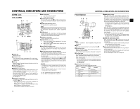
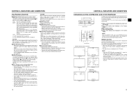
CONTROLS, INDICATORS AND CONNECTORS Right Side Section 2 1 54 3 7 6 8 9 0 a b c d VF BRIGHT USER 1 USER 2 USER 3 ND FILTER 2 1 MENU STATUS WHT.BAL AUTO AUTO AUDIO CH-1 LEVEL CH-2 ON OFF POWER REC e f gh j i 1Monitoring speaker (Cheek pad) • In the Camera mode, the input sound can be EE monitored. In the VTR mode, the speaker outputs the VTR playback sound. The sound to be output is selected with the MONITOR SELECT switch e on page 18. • The sound level is adjusted with the MONITOR sound level volume 3. This speaker also outputs various warning sounds superimposed on other sound. X See "Alarm Sound" on page 91. 2Cheek pad set screw Screw for adjusting the height of the cheek pad. 3[MONITOR] Audio monitor volume control Adjusts the volume of the monitoring loudspeaker and earphone. 4[VF BRIGHT] Viewfinder brightness adjustment To adjust the brightness of the viewfinder. X See page 43. 5[PEAKING] Contour adjustment To adjust the contours of the LCD monitor and viewfinder image. * When the Focus Assist function is running, this control does not operate. X See page 43. 6[FOCUS ASSIST] Focus assist button When you press this button during shooting, the area of focus is displayed in blue, red or green, making it easy to focus accurately. X See "LCD/VF [1/3] Menu Screen" on page 74. 7Clamp Attach the cable from the viewfinder here. 8[USER1/2/3] User buttons You can assign camera functions to the USER1 - 3 buttons. Use them to switch shooting conditions depending upon the subject. Set them using the USER1 - 3 items in the SWITCH MODE menu screen. X See page 71. MEMO • The USER buttons work together with the menu settings. • When a menu screen is being displayed, they also func- tion as menu operation buttons. X See "Setting Menu Screens" on page 62. 9[SHUTTER] Shutter/Menu dial • Every time this dial is pressed while in the normal screen mode (when the menu screen is not displayed), the shutter speed switches between on/off. • When this dial is turned 1 click up or down in the normal screen mode, the shutter speed indicator is shown for about 3 seconds on the LCD monitor or in the viewfinder. The shutter speed is changed when this dial is turned while the shutter speed indicator is shown. X See page 71. • When this dial turned upward or downward while the menu screen is displayed, the cursor (K) also moves upward or downward to allow selection of items in the menu. To change the setting value of the item, press this dial. When the setting value starts blinking, turn this dial upward or downward to change the setting. X See "Setting Menu Screens" on page 62. 0[ND FILTER] ND filter switch Switches the built-in ND filter. OFF : Turns the filter OFF (FILTER OFF) 1 : Cuts the light intensity to approximately 1/4. (1/4ND) 2 : Cuts the light intensity to approximately 1/16. (1/16ND) When you change this switch, the type of the new ND filter is displayed in the LCD monitor or viewfinder. CAUTION If you switch the ND filter while shooting is in progress, the picture may be disturbed or noise may occur in the audio. X See "Camera Settings" on page 47. a[STATUS] Status/Menu button • Pressing this button in the normal screen mode (condition in which the menu screen is not shown) displays a status screen in the viewfinder or on the LCD monitor. The displayed status screen changes each time the button is pressed. X See "Status Screens" on page 19. • Pressing this button for more than 1 second in the normal screen mode displays the menu screen in the viewfinder or on the LCD monitor. Pressing this button while the menu screen is displayed in the viewfinder or on the LCD monitor makes the menu screen disappear. X See "Setting Menu Screens" on page 62. CONTROLS, INDICATORS AND CONNECTORS b[GAIN] Sensitivity selector switch Electronically boosts the light sensitivity when there is insufficient illumination on the subject. The boosting level differs depending on the switch position as follows: (Factory presets) L : 0 dB (no boosting is applied) M : 9 dB (boosted to approximately 3 times the original) H : 18 dB (boosted to approximately 8 times the original) • The boosting level for each switch position can be changed with the SWITCH MODE menu screen. X See page 71. The more the boosting level is increased, the more the resulting image will be noisy. • When the FULL AUTO switch h on page 18 is "ON", this is fixed at "ALC". c[WHT.BAL] White balance switch Three white balance modes are selectable with this switch. B : Switch into white balance mode memorized in B. If white balance is performed with the switch in this position, it will be memorized into B. A : Switch into white balance mode memorized in A. If white balance is performed with the switch in this position, it will be memorized into A. PRST : Switch into white balance mode (3200K or (PRESET) 5600K) set in PRESET TEMP. item on the CAMERA OPERATION menu screen. X See page 66. FAW (Full Auto White Balance) mode can be set to A, B or PRESET with the SWITCH MODE menu screen. X See page 71. In the FAW mode, video color temperatures are constantly sampled for automatic adjustment to a proper white balance. • When the FULL AUTO switch h on page 18 is "ON", this is fixed at "FAW". dStand When attaching the lens, slide the stand forward. CAUTION There is a risk that the camcorder will fall onto the viewfinder side when the lens is not attached, so leave the lens attached even if you are not using it. e[POWER] Power ON/OFF switch Switch that turns the power ON/OFF. When the power is OFF, "POFF" is displayed in the LCD monitor or viewfinder. * Wait at least 5 seconds if you need to turn the power on again. f[REC] REC trigger button (start/stop recording) Start and stop recording using this button. (This works together with the REC trigger button on the top and the lens VTR trigger button.) When "SPLIT" is set for the 1394 REC TRIGGER item on the OTHERS [2/2] menu screen, this button becomes the start/stop recording button for an external device. X See page 81. X See "Backup Recording" on page 60. g[CH-1/CH-2 AUDIO LEVEL] CH-1/CH-2 Audio level controls and AUTO LED Allow you to adjust the audio level for the CH-1 and CH-2 audio channels. • To use these controls, set the CH-1/CH-2 AUDIO SELECT switch 2 on page 13 to "MANUAL". • When the FULL AUTO switch h on page 18 or the CH1/CH-2 AUDIO SELECT switch 2 on page 13 is set to "AUTO", "AUTO LED" lights. (The audio level controls do not work.) h[HDV/DV LED] • In camera mode, this lights according to the setting for the video format being shot. • In VTR mode, it lights according to the video format being recorded on tape or the IEEE1394 input video format. HDV : Lights when the format is HDV. DV : Lights when the format is DV. MEMO • During a system error, HDV/DV flash alternately. X See page 90. • Select whether or not to have this light in the FORMAT LED item on the OTHERS [1/2] menu screen. X See page 80. iLCD door lock and release knob To open the LCD door, move this knob on the direction toward the rear section. jLCD door LCD monitor door. The LCD monitor is located on the inner side of the door. The LCD monitor can be viewed when this door is opened. The door can be turned to change the orientation of the LCD monitor, and it can be rotated so that it can be accommodated in the main body of the camera. X See page 43. 14 15
-
 1
1 -
2
-
3
-
4
-
 5
5 -
 6
6 -
 7
7 -
 8
8 -
 9
9 -
 10
10 -
 11
11 -
 12
12 -
 13
13 -
 14
14 -
 15
15 -
16
-
17
-
18
-
19
-
20
-
21
-
22
-
23
-
24
-
25
-
26
-
27
-
28
-
29
-
30
-
31
-
32
-
33
-
34
-
35
-
36
-
37
-
38
-
39
-
40
-
41
-
42
-
43
-
44
-
45
-
46
-
47
-
48
-
49
-
50
-
51
 |
 |
