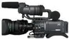
JVC GYHD110U Instructions - Page 16
Magnified Status Indications on the LCD Monitor - gy hd110 manual
 |
UPC - 046838027345
View all JVC GYHD110U manuals
Add to My Manuals
Save this manual to your list of manuals |
Page 16 highlights
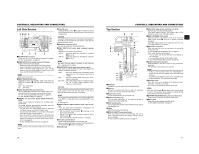
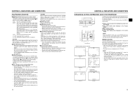
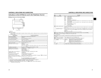
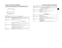
CONTROLS, INDICATORS AND CONNECTORS Indications on the LCD Monitor and in the Viewfinder (Cont'd) „ Magnified Status Indications on the LCD Monitor The characters on the status screens can be showed alone in magnified size on the LCD monitor. * When this unit is being operated with an Anton Bauer battery or IDX battery, characters are displayed in magnified size. 1 DISPLAY button LCD BRIGHT CAHU-1DIOSELECT AUTO CH-2 MANU CAM/VTR TC DISPLAY TC GENE. UB RFRECEE REGEN 2 3 266S DD 4 1. Set the LCD+VF item on the LCD/VF [3/3] menu screen to ON. (X See page 76.) 2. When the DISPLAY button is pressed for a short time while the LCD monitor is displayed, the displayed contents change every time the DISPLAY button is pressed. (Only when operating the GY-HD110 with the Anton-Bauer or IDX battery). Only image displayed Characters shown enlarged Image and characters displayed No. Item Contents 1 Audio Lock Indicator Displayed during recording and playback when the audio signal is locked to the video signal. 2 Time Code Generator Setting Indicates the set status of the TC GENE switch on the side section. Indicator FREE : TC GENE switch is set to PRESET-FREE RUN MODE. RECR : TC GENE switch is set to PRESET-REC RUN MODE. REGN : TC GENE switch is set to REGEN MODE. DUPL : There is 1394 input in VTR mode and TC DUPLI. menu is set to ON. 3 Drop/Non-drop Indicator Displayed during playback of a tape recorded in drop frame or non-drop frame mode. DF : During playback of a tape recorded in drop frame mode. NDF : During playback of a tape recorded in non-drop frame mode. 4 Indication of DR-HD100 Oper- When a DR-HD100 (HDD unit by FOCUS enhancements) is connected, its operation status is displayed. ation (For details, refer to the DR-HD100 INSTRUCTION MANUAL.) MEMO When characters indicating the status are displayed in magnified size on the LCD monitor, the viewfinder display the image. CONTROLS, INDICATORS AND CONNECTORS „ Auto White Balance Indication (Camera mode only) The AUTO WHITE indication and the result of the operation are displayed during the auto white balance adjustment operation. X See "White Balance Adjustment" on page 45. „ Menu Setting Screen Screen used for making various settings. The Menu Setting Screen appears when the STATUS button is pressed for 1 second or more. X See "Setting Menu Screens" on page 62. TOP MENU screen (Camera mode) Alarm display area „ Alarm Message Display • The following alarm messages are displayed while the STATUS (0, 1, 4) screen is shown in the Camera mode, or a STATUS screen is shown in the VTR mode. If an alarm is generated while the STATUS 2, 3 screen is shown, the STATUS 0 screen returns to display the alarm. X See page 89. • When an abnormality occurs in the VTR, a warning mes- sage with an error code is displayed. X See page 89-90. „ Safety Zone Indication (Camera mode only) The indication of the following safety zone and center mark indications can be turned ON/OFF with the SAFETY ZONE item and CENTER MARK item on the LCD/VF [1/3] menu screen. X See page 74. In addition, the safety zone display is on or off depending on the REC item setting and the ASPECT item setting in the VIDEO FORMAT menu screen, as shown below. SAFETY ZONE CENTER MARK REC ASPECT DV-60I DV-24P 4:3 DV-24PA DV-50I DV-25P 16:9 HDV-SD60P HDV-SD50P HDV-HD30P HDV-HD25P HDV-HD24P [16:9] OFF - 4:3 OFF ON 14:9 OFF ON 16:9 OFF ON 16:9+4:3 OFF ON Cannot be selected 26 27
-
 1
1 -
2
-
3
-
4
-
5
-
6
-
7
-
8
-
9
-
10
-
 11
11 -
 12
12 -
 13
13 -
 14
14 -
 15
15 -
 16
16 -
 17
17 -
 18
18 -
 19
19 -
 20
20 -
 21
21 -
22
-
23
-
24
-
25
-
26
-
27
-
28
-
29
-
30
-
31
-
32
-
33
-
34
-
35
-
36
-
37
-
38
-
39
-
40
-
41
-
42
-
43
-
44
-
45
-
46
-
47
-
48
-
49
-
50
-
51
 |
 |
