Panasonic BT-4LH310 Parts List - Page 56
LCD GAMMA Measurement, 1. Connection, 2. Note for gamma measurement and calibration
 |
View all Panasonic BT-4LH310 manuals
Add to My Manuals
Save this manual to your list of manuals |
Page 56 highlights
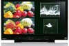
2. LCD GAMMA Measurement (Adjustment using LCD color analyzer) Take the following procedures to execute the adjustment when you use the color analyzer. 2-1. Connection M.EQ Color analyzer CA-210 (Konica Minolta), Probe CA-PU12 or CA-PU15 (Konica Minolta), Personal computer TOOLS RS-232C cable (9pin-9pin straight), RS-232C cable (9pin-9pin cross) or USB cable VSI5795(GAMMA Adjustment software) < Connection chart > LCD Monitor Probe PC CA-PU12 or *Measure the gamma by putting the CA-PU15 top of the probe at the center of LCD screen perpendicularly with no space. (Refer to the instructions of CA-210.) Cable of the Color analyzer attachment. Color analyzer CA-210 COM port RS-232C cable (9pin-9pin cross) or USB cable COM port RS-232C cable (9pin-9pin straight) 1. 1. Install the driver software, which is attached in CA-210, to the computer. (Execute the installation before connecting the LCD monitor. Refer to the instructions of CA-210 for details.) 2. Follow the above figure to connect the measuring devices with the cables. 3. Measure the gamma in a darkened room without light such as fluorescence lighting. 2-2. Note for gamma measurement and calibration Put the top of the probe to the center of LCD screen vertically without the space and measure the gamma. (Refer to the instructions of CA-210.) The probe and the LCD screen should face each other directly. Measurement Probe ADJ - 5
-
 1
1 -
2
-
3
-
4
-
5
-
6
-
7
-
8
-
9
-
10
-
11
-
12
-
13
-
14
-
15
-
16
-
17
-
18
-
19
-
20
-
21
-
22
-
23
-
24
-
25
-
26
-
27
-
28
-
29
-
30
-
31
-
32
-
33
-
34
-
35
-
36
-
37
-
38
-
39
-
40
-
41
-
42
-
43
-
44
-
45
-
46
-
47
-
48
-
49
-
50
-
 51
51 -
 52
52 -
 53
53 -
 54
54 -
 55
55 -
 56
56 -
 57
57 -
 58
58 -
 59
59 -
 60
60 -
 61
61 -
62
-
63
-
64
-
65
-
66
-
67
-
68
-
69
-
70
-
71
-
72
-
73
-
74
-
75
-
76
-
77
-
78
-
79
-
80
-
81
-
82
-
83
-
84
-
85
-
86
-
87
-
88
-
89
-
90
-
91
-
92
-
93
-
94
-
95
-
96
-
97
-
98
-
99
-
100
-
101
-
102
-
103
-
104
-
105
-
106
-
107
-
108
-
109
-
110
-
111
-
112
-
113
-
114
-
115
-
116
-
117
-
118
-
119
-
120
-
121
-
122
-
123
-
124
-
125
 |
 |
