Panasonic PT52LCX66 Service Manual - Page 14
Model No. Identification Mark, Hot Circuit, Do Not Unplug Ac Cord During, Cooling Operation, Clogged - user manual
 |
View all Panasonic PT52LCX66 manuals
Add to My Manuals
Save this manual to your list of manuals |
Page 14 highlights
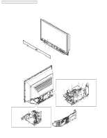
PT-52LCX66 / PT-56LCX66 / PT-61LCX66 / PT-52LCX16 / PT-56LCX16 RESET USER'S MEMORY FUNCTIONS Be sure to reset the user's memory: - After replacing the Digital Tuner P.C.B. - If the secret code for V-chip has been forgotten. - When moving the unit to a new location. - When resetting SOS (Error) number records. 1. Turn on the power. 2. Press and hold the VOLUME DOWN button on the unit and the OK key on the remote for more than 3 seconds. When reset is finished, power shuts off automatically (the user's memory is reset). CLOGGED AIR FILTER DETECTION When a dirty or clogged air filter is detected, the OSD display appears for 1 minute. And then the Lamp is turned OFF. When this OSD display appears, remove the Projection Unit from rear, and clean the air filters gently on the Projection Unit. AIR FILTER CLEANING IS RECOMMANDED AT THIS TIME. FIRST TURN THE UNIT OFF. PLEASE CALL FOR SERVICE. UNIT WILL BE TURNED OFF AFTER 1 MINUTE. DO NOT UNPLUG AC CORD DURING COOLING OPERATION The lamp cooling fan will continue to operate for approximately 1 minute after the power is turned off. At the same time, the POWER LED will flash red. Do not disconnect the AC Cord from the power outlet and do not open any circuit breakers while the cooling fan is still operating. HOT CIRCUIT Primary circuit exists on the Power P.C.B. This circuit is identified as "HOT" on the P.C.B. and in the Service Manual. Use extreme care to prevent accidental shock when servicing. MODEL NO. IDENTIFICATION MARK Use Marks shown in the chart below to distinguish the different models included in this Service Manual. MODEL MARK PT-52LCX66 A PT-56LCX66 B PT-61LCX66 C PT-52LCX16 D PT-56LCX16 E NOT USED PT Note: Refer to Item 3 of Schematic Diagram Notes of Schematic Diagram and Circuit Board Layout Notes, for mark "PT." 14
-
 1
1 -
2
-
3
-
4
-
5
-
6
-
7
-
8
-
 9
9 -
 10
10 -
 11
11 -
 12
12 -
 13
13 -
 14
14 -
 15
15 -
 16
16 -
 17
17 -
 18
18 -
 19
19 -
20
-
21
-
22
-
23
-
24
-
25
-
26
-
27
-
28
-
29
-
30
-
31
-
32
-
33
-
34
-
35
-
36
-
37
-
38
-
39
-
40
-
41
-
42
-
43
-
44
-
45
-
46
-
47
-
48
-
49
-
50
-
51
-
52
-
53
-
54
-
55
-
56
-
57
-
58
-
59
-
60
-
61
-
62
-
63
-
64
-
65
-
66
-
67
-
68
-
69
-
70
-
71
-
72
-
73
-
74
-
75
-
76
-
77
-
78
-
79
-
80
-
81
-
82
-
83
 |
 |
