Panasonic PT52LCX66 Service Manual - Page 34
Slide
 |
View all Panasonic PT52LCX66 manuals
Add to My Manuals
Save this manual to your list of manuals |
Page 34 highlights
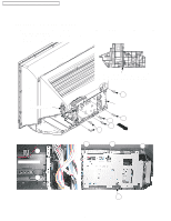
PT-52LCX66 / PT-56LCX66 / PT-61LCX66 / PT-52LCX16 / PT-56LCX16 2. Remove the Connecting Plate R by removing the 2 Screws (401, 402). 3. 1) Remove the 2 Screws (402) on the Connecting Plate F, and remove the Screw (401) on the left side of the TV Unit. 2) Disconnect Connectors CN4501, CN6000, CN6001, CN6002, CN6008 and the 2 Speaker Connectors and release from the clampers. 3) To access the GND Wire of the LVDS Cable, slide the TV Unit with the Digital Tuner P.C.B. along the Guide Tabs. 4) Remove the Screw (402) on GND Wire of LVDS Cable, and disconnect the LVDS Cable from Connector CN5700. Note: refer to next page. 5) Remove the TV Unit with the Digital Tuner P.C.B. Guide Tabs (x2) Connecting Plate F TV Unit with Digital Tuner P.C.B. Speaker Connectors 402 402 GND Wire of LVDS Cable Slide 401 Connecting Plate R CN5700 CN6001 CN6000 (From LCD (From Power (From Power Drive P.C.B.) Switch P.C.B.) P.C.B.) 401 402 402 CN6008 (From LCD Drive P.C.B.) Connecting Plate F CN6002 (From Power 402 P.C.B.) Clamper 401 Speaker Connectors CN4501 (From Power P.C.B.) Fig. D1-2 34
-
 1
1 -
2
-
3
-
4
-
5
-
6
-
7
-
8
-
9
-
10
-
11
-
12
-
13
-
14
-
15
-
16
-
17
-
18
-
19
-
20
-
21
-
22
-
23
-
24
-
25
-
26
-
27
-
28
-
 29
29 -
 30
30 -
 31
31 -
 32
32 -
 33
33 -
 34
34 -
 35
35 -
 36
36 -
 37
37 -
 38
38 -
 39
39 -
40
-
41
-
42
-
43
-
44
-
45
-
46
-
47
-
48
-
49
-
50
-
51
-
52
-
53
-
54
-
55
-
56
-
57
-
58
-
59
-
60
-
61
-
62
-
63
-
64
-
65
-
66
-
67
-
68
-
69
-
70
-
71
-
72
-
73
-
74
-
75
-
76
-
77
-
78
-
79
-
80
-
81
-
82
-
83
 |
 |
