Panasonic PT52LCX66 Service Manual - Page 41
Removal Of The Front Jack/operation P.c.b., The Sd Card P.c.b., The Main, P.c.b., The Base P.c.b.
 |
View all Panasonic PT52LCX66 manuals
Add to My Manuals
Save this manual to your list of manuals |
Page 41 highlights
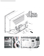
PT-52LCX66 / PT-56LCX66 / PT-61LCX66 / PT-52LCX16 / PT-56LCX16 REMOVAL OF THE FRONT JACK/OPERATION P.C.B., THE SD CARD P.C.B., THE MAIN P.C.B., THE BASE P.C.B. FROM THE TV UNIT 1. Remove the TV Unit. Refer to Steps 1 ~ 4 in "REMOVAL OF THE TV UNIT AND THE DIGITAL TUNER P.C.B. FROM THE CABINET." 2. Remove the Rear Jack Holder by removing the screws and releasing Locking tab (" " mark). 3. Remove the Main P.C.B. and the Main PCB Mount Metal together by removing the screws (" " mark) and the connector. Then remove the Main P.C.B. by removing the screws (" " mark). 4. Remove the Base P.C.B. by removing the screws (" " mark). 479 Base P.C.B. E20 This screw is deleted on a 402 85 running change basis. 479 479 479 479 479 25 402 402 402 479 479 479 402 479 402 402 Connector 752 E60 SD Card P.C.B. 359 75 95 80 95 80 95 Main PCB 402 M3o59unt Metal 82 E10 Main P.C7.4B. 95 402 81 81 452 452 81 402 452 81 E50 Front Jack /Operation P.C.B. 229 81 76 Locking Rear tab Jack Holder 452 402 402 77 402 (D,E,F,G,H) 452 84 72 84 84 84 84 84 41
-
 1
1 -
2
-
3
-
4
-
5
-
6
-
7
-
8
-
9
-
10
-
11
-
12
-
13
-
14
-
15
-
16
-
17
-
18
-
19
-
20
-
21
-
22
-
23
-
24
-
25
-
26
-
27
-
28
-
29
-
30
-
31
-
32
-
33
-
34
-
35
-
 36
36 -
 37
37 -
 38
38 -
 39
39 -
 40
40 -
 41
41 -
 42
42 -
 43
43 -
 44
44 -
 45
45 -
 46
46 -
47
-
48
-
49
-
50
-
51
-
52
-
53
-
54
-
55
-
56
-
57
-
58
-
59
-
60
-
61
-
62
-
63
-
64
-
65
-
66
-
67
-
68
-
69
-
70
-
71
-
72
-
73
-
74
-
75
-
76
-
77
-
78
-
79
-
80
-
81
-
82
-
83
 |
 |
