Panasonic PT52LCX66 Service Manual - Page 39
Power P.C.B., Power PCB, Mount Metal - pt 52lcx66 k lamp
 |
View all Panasonic PT52LCX66 manuals
Add to My Manuals
Save this manual to your list of manuals |
Page 39 highlights
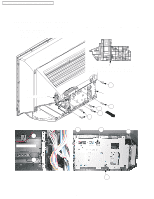
PT-52LCX66 / PT-56LCX66 / PT-61LCX66 / PT-52LCX16 / PT-56LCX16 REMOVAL OF THE POWER P.C.B. FROM THE CABINET 1. Remove the Rear Cover Unit. Refer to Step 1 in "REMOVAL OF THE TV UNIT AND THE DIGITAL TUNER P.C.B. FROM THE CABINET." 2. 1) Open the Power P.C.B/Power PCB Mount Metal by removing the 6 Screws (402, 421). 2) Disconnect Connectors CN1522, CN1514, CN1516, CN1520 (Thermal Fuse) and release from the clampers. 3) Remove the Lamp Unit by turning the Knob from the front. 3. 1) Disconnect the Lamp Connector by removing the 2 Screws (451). Power PCB Mount Metal Knob Lamp Power P.C.B. /Power PCB Mount Metal 402 Open 421 402 421 421 This screw is deleted on a running change basis. 421 402 Lamp Connector Power P.C.B. 451 451 402 421 421 421 421 CN1516 CN1001 CN1522 (AC Cord) (From CN1514 CN1520 (From Base (From (From P.C.B.) This screw is Main Main Thermal deleted on a P.C.B.) P.C.B.) Fuse) running change basis. Fig. D4-1 Reassembly Note for Lamp: After installing the Lamp Unit, confirm that the Lamp Unit will not come out by pulling on the Knob. 39
-
 1
1 -
2
-
3
-
4
-
5
-
6
-
7
-
8
-
9
-
10
-
11
-
12
-
13
-
14
-
15
-
16
-
17
-
18
-
19
-
20
-
21
-
22
-
23
-
24
-
25
-
26
-
27
-
28
-
29
-
30
-
31
-
32
-
33
-
 34
34 -
 35
35 -
 36
36 -
 37
37 -
 38
38 -
 39
39 -
 40
40 -
 41
41 -
 42
42 -
 43
43 -
 44
44 -
45
-
46
-
47
-
48
-
49
-
50
-
51
-
52
-
53
-
54
-
55
-
56
-
57
-
58
-
59
-
60
-
61
-
62
-
63
-
64
-
65
-
66
-
67
-
68
-
69
-
70
-
71
-
72
-
73
-
74
-
75
-
76
-
77
-
78
-
79
-
80
-
81
-
82
-
83
 |
 |
