Panasonic PT52LCX66 Service Manual - Page 3
Safety Precautions - lamp
 |
View all Panasonic PT52LCX66 manuals
Add to My Manuals
Save this manual to your list of manuals |
Page 3 highlights
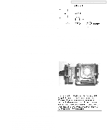
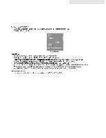
1 Safety Precautions PT-52LCX66 / PT-56LCX66 / PT-61LCX66 / PT-52LCX16 / PT-56LCX16 1.1. General Guidelines 1. For continued safety, no modification of any circuit should be attempted. 2. Disconnect AC Plug before disassembling this unit. 3. It is advisable to use an isolation transformer in the AC supply before servicing. 4. When servicing, observe the original lead dress. If a short circuit is found, replace all parts which have been overheated or damaged by the short circuit. 5. After servicing, see to it that all the protective devices such as insulation barriers, insulation papers, shield, and isolation R-C combinations etc. are properly installed. 6. After servicing, be sure to restore the wires, leads, insulation barriers, shields, etc. 7. After servicing, make the leakage current checks to prevent the customer from being exposed to shock hazards. Caution: Use a separate Isolation Transformer for this unit when servicing. 1.2. Leakage Current Cold Check Figure 1 1.4. UV-Precaution 1. Be sure to disconnect the AC Plug when replacing the lamp. 2. Since the lamp reaches a very high temperature during its operation, wait until it has completely cooled off when replacing the Lamp Unit. 3. The lamp emits small amounts of UV-Radiation. Avoid direct-eye contact by covering the Lamp and wearing the UV protective glasses. 4. The high pressure lamp involves a risk of explosion. 1. Unplug the AC cord and connect a jumper between the two prongs on the plug. 2. For physically operated power switches, turn power on. Otherwise skip step 2. 3. Measure the resistance value, with an ohmmeter, between the jumpered AC plug and each exposed metallic cabinet part on the receiver, such as screwheads, connectors, etc. When the exposed metallic part has a return path to the chassis, the reading should be between 1 MΩ and 12 MΩ. When the exposed metal does not have a return path to the chassis, the reading must be infinity. Figure 2 1.3. Leakage Current Hot Check 1. Plug the AC cord directly into the AC outlet. Do not use an isolation transformer for this check. 2. Connect "A" to exposed metallic part on the set. And connect "B" to a good earth ground, as shown in Figure 1. 3. Use an AC voltmeter, with 1 kΩ/V or more sensitivity, to measure the potential across the resistor. 4. Check each exposed metallic part, and measure the voltage at each point. 5. Reverse the AC plug in the AC outlet and repeat each of the above measurements. 6. The potential at any point should not exceed 0.25 V RMS. A leakage current tester (Simpson Model 228 equivalent) may be used to make the hot checks. Leakage current must not exceed 1/2 mA. In case a measurement is outside of the limits specified, there is a possibility of shock hazard, and the receiver should be repaired and rechecked before it is returned to the customer. 3
-
 1
1 -
 2
2 -
 3
3 -
 4
4 -
 5
5 -
 6
6 -
 7
7 -
 8
8 -
 9
9 -
10
-
11
-
12
-
13
-
14
-
15
-
16
-
17
-
18
-
19
-
20
-
21
-
22
-
23
-
24
-
25
-
26
-
27
-
28
-
29
-
30
-
31
-
32
-
33
-
34
-
35
-
36
-
37
-
38
-
39
-
40
-
41
-
42
-
43
-
44
-
45
-
46
-
47
-
48
-
49
-
50
-
51
-
52
-
53
-
54
-
55
-
56
-
57
-
58
-
59
-
60
-
61
-
62
-
63
-
64
-
65
-
66
-
67
-
68
-
69
-
70
-
71
-
72
-
73
-
74
-
75
-
76
-
77
-
78
-
79
-
80
-
81
-
82
-
83
 |
 |
