Panasonic PT52LCX66 Service Manual - Page 32
Disassembly and Assembly Instructions - power supply
 |
View all Panasonic PT52LCX66 manuals
Add to My Manuals
Save this manual to your list of manuals |
Page 32 highlights
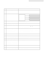
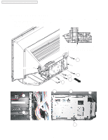
PT-52LCX66 / PT-56LCX66 / PT-61LCX66 / PT-52LCX16 / PT-56LCX16 8 Disassembly and Assembly Instructions 8.1. Cabinet Section DISASSEMBLY METHOD OF CABINET SECTION Cabinet section contains following removal procedures: REMOVAL OF THE TV UNIT AND THE DIGITAL TUNER P.C.B. FROM THE CABINET REMOVAL OF THE PROJECTION UNIT REMOVAL OF THE BASE BODY UNIT REMOVAL OF THE POWER P.C.B. FROM THE CABINET REMOVAL OF THE FRONT JACK/OPERATION P.C.B., THE SD CARD P.C.B., THE MAIN P.C.B., THE BASE P.C.B. FROM THE TV UNIT REMOVAL OF THE SCREEN UNIT FROM THE DISPLAY REMOVAL OF THE MIRROR FROM THE BACK COVER REMOVAL OF THE POWER SWITCH P.C.B. FROM THE CABINET DISASSEMBLY FLOWCHART This flow chart indicates the disassembly steps of the cabinet parts and the P.C.Boards in order to gain access to item (s) to be serviced. When reassembling, perform the step (s) in the reverse order. Bend, route and dress the wires as they were originally. FRONT COVER UNIT REAR COVER (DISPLAY) SCREEN UNIT MIRROR BACK COVER BASE BODY UNIT POWER P.C.B. DIGITAL TUNER P.C.B. PROJECTION UNIT POWER SWITCH P.C.B. TV UNIT FRONT JACK /OPERATION P.C.B. SD CARD P.C.B. MAIN P.C.B. BASE P.C.B. Note : a. Place a cloth or some other soft material under the P.C. Boards or Unit to prevent damage. b. When reinstalling, ensure that the connectors are connected firmly and electrical components have not been damaged. c. Do not supply power to the unit during disassembly and reassembly. 32
-
 1
1 -
2
-
3
-
4
-
5
-
6
-
7
-
8
-
9
-
10
-
11
-
12
-
13
-
14
-
15
-
16
-
17
-
18
-
19
-
20
-
21
-
22
-
23
-
24
-
25
-
26
-
 27
27 -
 28
28 -
 29
29 -
 30
30 -
 31
31 -
 32
32 -
 33
33 -
 34
34 -
 35
35 -
 36
36 -
 37
37 -
38
-
39
-
40
-
41
-
42
-
43
-
44
-
45
-
46
-
47
-
48
-
49
-
50
-
51
-
52
-
53
-
54
-
55
-
56
-
57
-
58
-
59
-
60
-
61
-
62
-
63
-
64
-
65
-
66
-
67
-
68
-
69
-
70
-
71
-
72
-
73
-
74
-
75
-
76
-
77
-
78
-
79
-
80
-
81
-
82
-
83
 |
 |
