Panasonic PT52LCX66 Service Manual - Page 15
Before Removing The Main P.c.b. Or, The Tv Unit From The Unit At The, Use's Location, When - lamp replacement
 |
View all Panasonic PT52LCX66 manuals
Add to My Manuals
Save this manual to your list of manuals |
Page 15 highlights
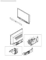
PT-52LCX66 / PT-56LCX66 / PT-61LCX66 / PT-52LCX16 / PT-56LCX16 BEFORE REMOVING THE MAIN P.C.B. OR THE TV UNIT FROM THE UNIT AT THE USE'S LOCATION Note: The TV Unit includes the Main P.C.B. CAUTION: 1. Be sure to make a note of the CURRENT LAMP value (value A) in Service Mode (1/4): SERVICE Mode 1/4 LAMP OPERATION TIME CURRENT LAMP: OSD DISP : LON COUNT : BKSV: 4B 7E 3D 2000h ON 153 CA FB Value A (Changeable) WHEN REINSTALLING THE MAIN P.C.B. OR THE TV UNIT FROM THE UNIT AT THE USE'S LOCATION CAUTION: 1. Set CURRENT LAMP value to original value as follows. 1) Select CURRENT LAMP in Service Mode (1/4). 2) Press the VOLUME UP/DOWN key on the remote to change to the original value (value A) that was noted before removing the Main P.C.B. or the TV Unit at the user's location. SERVICE Mode 1/4 LAMP OPERATION TIME CURRENT LAMP: OSD DISP : LON COUNT : BKSV: 48 BF 9D 2000h ON 153 72 B5 Value A (Changeable) Fig. 2 LAMP OPERATION TIME is stored in EEPROM on the Main P.C.B. Therefore, before removing the Main P.C.B. or the TV Unit at the user's location, make a note of the CURRENT LAMP value (value A) in Service Mode (1/4). Then, after installing the new Main P.C.B. or the TV Unit at the user's location, set the CURRENT LAMP value to the original value (value A) in Service Mode. Otherwise, OSD and LED Lamp replacement indications will be displayed at the wrong time. Note: In case it is impossible to make a note of the CURRENT LAMP value because of a defective Main P.C.B., ask the customer their daily average use and the approximate age of the current Lamp. Then, calculate the CURRENT LAMP value as follows and make a note. Daily average use (hours) X Approx. age (days) = CURRENT LAMP (hours) Note: The TOTAL value can be set to the original value in Service Mode (2/4) by similar method: Before removing the Main P.C.B. at the user's location, make a note of the TOTAL value in Service Mode (2/4). Then, after installing the new Main P.C.B. at the user's location, set the TOTAL value to the original value in Service Mode. 15 Fig. 3 Service Mode Map Enter: VOLUME DOWN button + TV/VIDEO key (on the front) (on the remote) (for more than 5 seconds in power off condition) Power ON SERVICE Mode 1/4 LAMP OPERATION TIME CURRENT LAMP: OSD DISP : LON COUNT : BKSV: B0 3A 59 2000h ON 153 CD 66 BKSV number < Service Mode (1/4) > CH DOWN key CH UP key SERVICE Mode IR:1 IC2301:1 3101:1 4504:1 5000:1 5801:1 6000:1 2/4 UNIT:1 4002:1 5001:1 9502:1 TOTAL TU8200:1 IC6001 : 12345h E:06030301 V:0005024 < Service Mode (2/4) > CH DOWN key CH UP key SERVICE Mode IC6001 PORT P0:10101010 P1:-1111100 P2:00000000 P3:00000000 P4:--111110 P5:10110101 P6:01011001 P7:10101001 3/4 P8:---10110 P9:--111111 PA:00000000 PB:11111110 PC:11111100 PD:-----111 PE:11000000 PF:----0011 < Service Mode (3/4) > CH DOWN key CH UP key SERVICE Mode 4/4 -SOS- LAST SOS H10SAFE 01 SAFE 10.40.50.50.40 H10SOS2 :01 H20FANST:00 H30DT5V :00 H40ACLST:00 H50GC4PR:01 Exit: Power OFF. < Service Mode (4/4) > CH DOWN key
-
 1
1 -
2
-
3
-
4
-
5
-
6
-
7
-
8
-
9
-
 10
10 -
 11
11 -
 12
12 -
 13
13 -
 14
14 -
 15
15 -
 16
16 -
 17
17 -
 18
18 -
 19
19 -
 20
20 -
21
-
22
-
23
-
24
-
25
-
26
-
27
-
28
-
29
-
30
-
31
-
32
-
33
-
34
-
35
-
36
-
37
-
38
-
39
-
40
-
41
-
42
-
43
-
44
-
45
-
46
-
47
-
48
-
49
-
50
-
51
-
52
-
53
-
54
-
55
-
56
-
57
-
58
-
59
-
60
-
61
-
62
-
63
-
64
-
65
-
66
-
67
-
68
-
69
-
70
-
71
-
72
-
73
-
74
-
75
-
76
-
77
-
78
-
79
-
80
-
81
-
82
-
83
 |
 |
