Sony HCD-FL7D Operating Instructions - Page 11
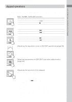
Refer to the print on your system's, VOLTAGE SELECTOR for available, settings., Set up the AM loop
 |
View all Sony HCD-FL7D manuals
Add to My Manuals
Save this manual to your list of manuals |
Page 11 highlights
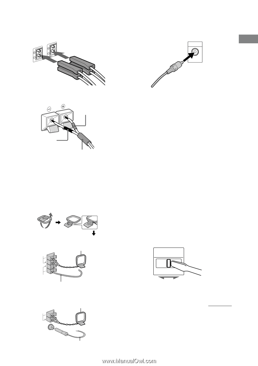
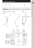
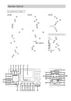
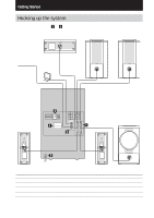
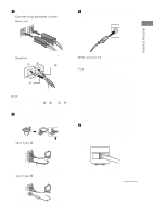
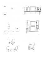
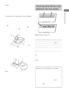
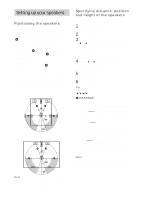
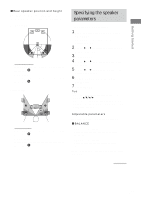
1 Connect the speakers. Connecting speaker cords Main unit 3 Connect the video input jack of your TV to the VIDEO OUT jack with the video cable. Getting Started Speaker Red(3) Black (#) Color tube Note Be sure to match the speaker cord to the appropriate terminal on the components: 3 to 3, and # to #. If the cords are reversed, the sound will be distorted and will lack bass. 2 Connect the FM/AM antennas. Set up the AM loop antenna, then connect it. Jack type A AM AM loop antenna When using a TV Turn on the TV and select the video input so you can view the pictures from this system. Tips • For even higher quality video images; - Use an optional component video cable to connect the COMPONENT VIDEO input jacks on your TV to the COMPONENT VIDEO OUT jacks of this system. If your TV is compatible with progressive format file signals, use this connection and set "COMPONENT OUT" to "PROGRESSIVE" in "SCREEN SETUP" (page 28). - Use an optional S-video cable to connect the S VIDEO input jack on your TV to the S VIDEO OUT jack of this system. • If you connect a video deck between this unit and the TV, you may experience video leakage when watching the video signal from this unit. Do not connect a video deck between this unit and the TV. 4 For models with a voltage selector, set VOLTAGE SELECTOR to the position of your local power line voltage. Refer to the print on your system's VOLTAGE SELECTOR for available settings. VOLTAGE SELECTOR FM 75Ω Extend the FM lead antenna horizontally. Jack type B AM AM loop antenna 120V* 220V 230240V * Saudi Arabian Model 120 -127 V continued CFOMA7X5IAΩL Extend the FM lead antenna horizontally. 11GB
-
 1
1 -
2
-
3
-
4
-
5
-
 6
6 -
 7
7 -
 8
8 -
 9
9 -
 10
10 -
 11
11 -
 12
12 -
 13
13 -
 14
14 -
 15
15 -
 16
16 -
17
-
18
-
19
-
20
-
21
-
22
-
23
-
24
-
25
-
26
-
27
-
28
-
29
-
30
-
31
-
32
-
33
-
34
-
35
-
36
-
37
-
38
-
39
-
40
-
41
-
42
-
43
-
44
-
45
-
46
-
47
-
48
-
49
-
50
-
51
-
52
-
53
-
54
-
55
-
56
-
57
-
58
-
59
-
60
-
61
-
62
-
63
-
64
-
65
-
66
-
67
-
68
-
69
-
70
-
71
-
72
-
73
-
74
-
75
-
76
 |
 |