Sony HDWM2100/20 Operation Manual
Sony HDWM2100/20 Manual
 |
View all Sony HDWM2100/20 manuals
Add to My Manuals
Save this manual to your list of manuals |
Sony HDWM2100/20 manual content summary:
- Sony HDWM2100/20 | Operation Manual - Page 1
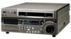
HD DIGITAL VIDEOCASSETTE PLAYER HDW-M2100 HDW-M2100P OPERATION MANUAL [English] 1st Edition (Revised 5) - Sony HDWM2100/20 | Operation Manual - Page 2
the user to the presence of important operating and maintenance (servicing) instructions in the literature accompanying the appliance. For the customers in the , if not installed and used in accordance with the instruction manual, may cause harmful interference to radio communications. Operation of - Sony HDWM2100/20 | Operation Manual - Page 3
WARNING: THIS WARNING IS APPLICABLE FOR OTHER COUNTRIES. 1. Use the approved Power Cord (3-core mains)/Appliance Connector/Plug with earthing-contacts that conforms to the safety regulations of each country if applicable. 2. Use the Power Cord (3-core mains lead)/Plug conforming to the following - Sony HDWM2100/20 | Operation Manual - Page 4
Table of Contents Chapter 1 Overview Chapter 2 Location and Function of Parts Chapter 3 Preparations Chapter 4 Playback Chapter 5 Shot Mark Function Chapter 6 Tele-File 1-1 Features 1-1 1-2 Example System Configuration 1-3 2-1 Control Panels 2-1 2-1-1 Upper Control Panel 2-2 2-1-2 Lower - Sony HDWM2100/20 | Operation Manual - Page 5
Table of Contents Chapter 7 UMID Functions Chapter 8 Function Menu Chapter 9 Setup Menus Chapter 10 Maintenance and Inspection Appendix 7-1 Overview of UMID Functions 7-1 7-2 UMID Output and Display 7-2 7-2-1 UMID Output Settings 7-2 7-2-2 UMID Display 7-2 8-1 Overview 8-1 8-1-1 Function Menu - Sony HDWM2100/20 | Operation Manual - Page 6
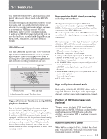
(HDCAM video/ audio data) (option) • Time code input/output • CUE audio output High quality four-channel audio High quality 20 bit/48 kHz AES/EBU digital audio is supported. There are four digital audio input/output channels, and four analog audio input/output channels. High-performance heads and - Sony HDWM2100/20 | Operation Manual - Page 7
connectors are provided, you can also control a number of VTRs simultaneously. Additionally, a parallel (50-pin) interface is also fitted as standard, supporting easy external control through the parallel interface. Rack mounting Using the optional RMM-131 Rack Mount Adaptor, you can mount the unit - Sony HDWM2100/20 | Operation Manual - Page 8
Chapter 1 Overview 1-2 Example System Configuration The following conceptual diagram shows an example of use. Digital cassette BVE-series editor Tape control HDW-M2100/M2100P SDTI (optional) HDSDI Audio/video server system HDSDI/Analog composite Video monitor Audio monitor Analog audio - Sony HDWM2100/20 | Operation Manual - Page 9
Chapter 2 LocaCthiapotenr 2 and Location Fandunct Functioniofon of Parts Parts 2-1 Control Panels There are three control panels, as follows: • Upper control panel • Lower control panel • Switch panel Z 59.94 CTL/TC MENU TC Upper control panel (see page 2-2) Lower control panel (see page 2-3) KEY - Sony HDWM2100/20 | Operation Manual - Page 10
set an internal board switch so that the output volume from the MONITOR OUTPUT L and R connectors is controlled simultaneously. For details, refer to the Installation Manual. - Sony HDWM2100/20 | Operation Manual - Page 11
Chapter 2 Location and Function of Parts 2-1-2 Lower Control Panel 4 Time data/menu display section (see page 2-6) 2 CHANNEL CONDITION indicator (see page 2-5) 5 MULTI CONTROL knob and PUSH/ SHIFT indicator (see page 2-7) 1 Audio control section (see page 2-4) 3 Menu control buttons (see page - Sony HDWM2100/20 | Operation Manual - Page 12
meters in the audio setting display section between FULL and FINE. FULL: The display covers the range -60 dB to 0 dB or -40 dB to +20 dB as selected using setup menu item 806. In this mode the segment of the display corresponding to the current audio level and all lower - Sony HDWM2100/20 | Operation Manual - Page 13
Chapter 2 Location and Function of Parts 3 Audio monitor signal selection buttons (CH1 to CH4, and CUE) The buttons in the upper and lower rows select tracks to be output to the MONITOR OUTPUT L and R connectors on the connector panel or the PHONES jack on the upper control panel. The buttons in - Sony HDWM2100/20 | Operation Manual - Page 14
Chapter 2 Location and Function of Parts 2-1 Control Panels 4 Time data/menu display section 1 Time data display 59.94 1 CTL/TC MENU TC 2 Menu display 1 Time data display This displays indicators relating to time data and other indicators. Time data display area 1 Time data type indicator DF - Sony HDWM2100/20 | Operation Manual - Page 15
Chapter 2 Location and Function of Parts DOLBY NR indicator This lights when the Dolby noise-reduction 1) circuit is functioning. Speed indication area This indicates the speed of a DMC playback. During a DMC playback, "DMC SPD" is displayed in time data display area 2. However, CONFI playback is - Sony HDWM2100/20 | Operation Manual - Page 16
2-1 Control Panels Chapter 2 Location and Function of Parts 2 JOG button To use the search dial for playback in jog mode, press this button, turning it on. For details of playback in jog mode, see the description of the search dial 5. 3 VAR (variable) button To use the search dial for playback in - Sony HDWM2100/20 | Operation Manual - Page 17
menu page 4 is ON, the error message also appears on the monitor screen. For details on error messages, refer to Section 1-24 in the Maintenance Manual Volume 1. KEY INHI (inhibit) indicator This indicator lights when the KEY INHI switch on the switch panel (see page 2-11) is set to ON. ...1) Stop - Sony HDWM2100/20 | Operation Manual - Page 18
Chapter 2 Location and Function of Parts 2-1 Control Panels q; Editing control section 1 DMC EDIT button 2 MEMORY indicator 3 DELETE button 4 TRIM buttons TRIM DMC EDIT DELETE MEMORY LEARN CUE/PLAY 5 DMC playback control point setting buttons IN PLAY OUT ENTRY IN STUNT OUT 7 LEARN button 6 - Sony HDWM2100/20 | Operation Manual - Page 19
Chapter 2 Location and Function of Parts 7 LEARN button After setting a speed variation start point (STUNT IN point) and a speed variation end point (STUNT OUT point), pressing this button makes the tape start running. You can then use the search dial to vary the tape speed, which is automatically - Sony HDWM2100/20 | Operation Manual - Page 20
save or load setup menu settings onto the memory card. For details on firmware update and setup menu reading/ storing, refer to the Maintenance Manual Volume 1. 2 Memory card ejection button Press to eject a memory card from the memory card slot. 3 CONTROL PANEL connector (10-pin, round type) Plug - Sony HDWM2100/20 | Operation Manual - Page 21
Chapter 2 Location and Function of Parts 2-2 Connector Panel Cooling fan 1 Analog audio output section 2 Analog video input/output section 3 Digital audio output section (see page 2-14) 75Ω 4 Digital signal output section (see page 2-14) Cooling fan 5 Power supply section (see page 2-15) 7 - Sony HDWM2100/20 | Operation Manual - Page 22
Chapter 2 Location and Function of Parts 2-2 Connector Panel 1 REF. (reference) VIDEO INPUT connectors (BNC type) and 75Ω termination switch Input a reference video signal. Input a three-valued (positive and negative) sync signal, a video signal with chroma burst (VBS) or a monochrome video signal - Sony HDWM2100/20 | Operation Manual - Page 23
1 REMOTE 2 PARALLEL I/O(50P) connector (D-sub 50-pin) Connect remote control signals from an external device. For details, refer to the Installation Manual. 2 CONTROL PANEL connector (round type, 10pin) In addition to the lower control panel, a similar control panel can be connected to this unit - Sony HDWM2100/20 | Operation Manual - Page 24
Chapter 2 Location and Function of Parts 2-2 Connector Panel 7 Time code output section TIME CODE OUT TIME CODE OUT connector TIME CODE OUT connector (XLR 3-pin, male) This outputs the playback time code. By setting setup menu item 606, you can also output the time code from the internal time - Sony HDWM2100/20 | Operation Manual - Page 25
Chapter 3 PreparationsChapter 3 Preparations 3-1 Connections to External Devices 3-1-1 Connections to Digital Devices The following example shows the connections with an HDW-2000/M2000/M2000P unit as a recorder, with this unit used as a player. REF. VIDEO INPUT Reference signal 75 Ω termination - Sony HDWM2100/20 | Operation Manual - Page 26
3-1 Connections to External Devices 3-1-2 Connecting Reference Signals Connect reference signals as shown below. SD video monitor 75 Ω termination switch: ON • SDI OUTPUT • COMPOSITE • COMPONENT 75Ω HD video monitor HDSDI OUTPUT HDW-M2100/M2100P REF. VIDEO INPUT Reference signal Chapter 3 - Sony HDWM2100/20 | Operation Manual - Page 27
Chapter 3 Preparations 3-2 Setup The principal setup operations before operating this unit can be carried out using setup menus. The setup menus of this unit comprise a basic setup menu and an extended setup menu. The contents of these menus are as follows. Basic setup menu: • Items relating to the - Sony HDWM2100/20 | Operation Manual - Page 28
3-3 Superimposed Character Information When the function menu item CHARA is set to ON, the video signal output from the HDSDI OUTPUT 3 (SUPER) connector, SDI OUTPUT 3 (SUPER) connector, or COMPOSITE VIDEO OUTPUT 3 (SUPER) connector contains superimposed character information, including time code, - Sony HDWM2100/20 | Operation Manual - Page 29
Chapter 3 Preparations 2 Time code reader drop frame mark (for 59.94i, 29.97PsF mode only) ".": Indicates drop frame mode ":": Indicates non-drop-frame mode 3 VITC field mark " " (blank): Fields 1 and 3 (for 59.94i, 29.97PsF mode) or fields 1, 3, 5 and 7 (for 50i, 25PsF mode) " * ": Fields 2 and 4 - Sony HDWM2100/20 | Operation Manual - Page 30
unit, pressing the EJECT button may not eject the cassette. For information about how to remove the cassette in such a case, refer to the Installation Manual. 1 Turn the POWER switch on. 3-6 Chapter 3 Preparations - Sony HDWM2100/20 | Operation Manual - Page 31
Chapter 3 Preparations 3-4-3 Preventing Accidental Recording of Shot Marks To prevent shot marks from being accidentally recorded on a tape, press in the red record inhibit plug on the cassette. Large cassette Small cassette Press in the red record inhibit plug. ("ON") Return this plug to its - Sony HDWM2100/20 | Operation Manual - Page 32
among cameras. Note Use a Memory Stick formatted with this VTR. It cannot be shared with other devices. For more details, refer to the Maintenance Manual. Inserting a Memory Stick Insert a Memory Stick with the label side up into the Memory Stick slot until it clicks. Types of Memory Stick There - Sony HDWM2100/20 | Operation Manual - Page 33
. Do not turn off the power of the camera or remove the Memory Stick. This may damage the data. For details, refer to the Maintenance Manual. Memory Stick and are the trademarks of Sony Corporation. MagicGate Memory Stick and are the trademarks of - Sony HDWM2100/20 | Operation Manual - Page 34
Chapter 4 Playback Chapter 4 Playback 4-1 Playback This section describes playback of video and audio. 4-1-1 Preparations for Playback Switch and menu settings Before beginning playback, make necessary switch and For details on each setting, see the pages indicated in menu settings. - Sony HDWM2100/20 | Operation Manual - Page 35
Chapter 4 Playback 4-1 Playback Time data selection Displayed time data Use the CTL/TC setting in function menu HOME page to select one of CTL (control), time code, and user bit values. When you select time code, the data displayed is determined by the F6 (TCR) setting (LTC/AUTO/ VITC) in - Sony HDWM2100/20 | Operation Manual - Page 36
Playback in jog mode In jog mode, you can control the speed of playback by the speed of turning the search dial. The playback speed range is ±1 times normal speed. The playback speed range can be ±3 times normal speed by changing the setting of setup menu item 116. To carry out playback in jog mode, - Sony HDWM2100/20 | Operation Manual - Page 37
4-1 Playback To return to normal-speed playback Press the PLAY button. To alternate between normal-speed playback and shuttle mode playback Set the search dial to the position corresponding to the desired shuttle playback speed, then switch between normal-speed playback and shuttle playback by - Sony HDWM2100/20 | Operation Manual - Page 38
To perform continuous capstan override playback Z 3 2 1 Set setup menu item 111 (TSO PLAY) to TSO. 2 Hold down the DMC EDIT button and turn the MULTI CONTROL knob to select the playback speed. The selected playback speed is displayed in time data display area 2 on the lower control panel of this - Sony HDWM2100/20 | Operation Manual - Page 39
Chapter 4 Playback 4-1 Playback 4-1-3 Dynamic Motion Control (DMC) Playback Overview DMC playback allows you to vary the playback speed for a certain section of a tape, in variable speed mode and store the varying speed in memory for later playback at the same varying speed. For example, during a - Sony HDWM2100/20 | Operation Manual - Page 40
3 Press the search dial or the SHUTTLE button or VAR button to enter shuttle/variable speed mode. Setting the initial speed to normal speed In step 4, press the PLAY button. The SHUTTLE/VAR indicator lights. Note Make sure that setup menu item 111 (TSO PLAY) is set to DIS. 4 Holding down the DMC - Sony HDWM2100/20 | Operation Manual - Page 41
Chapter 4 Playback 4-1 Playback To start playback immediately after preroll Press the LEARN button. The LEARN button lights, and after preroll, DMC playback is carried out for the section from the speed variation start point, then playback continues at normal speed from the speed variation end - Sony HDWM2100/20 | Operation Manual - Page 42
adjacent to the current tape position (index function). This unit reads in shot marks written on a tape and stores them in memory (to a maximum of 200). Once this data is stored in this unit, it is preserved even when the power is turned off. Writing and erasing shot marks Post marks - Sony HDWM2100/20 | Operation Manual - Page 43
5-2 Shot Mark Operation Menu This section describes the settings in the shot mark operation menu. Displaying the shot mark operation menu With the function menu HOME page showing in the menu display, hold down the MARK button, and press the F5 (MENU) button. Z F5 (MENU) button MARK button The - Sony HDWM2100/20 | Operation Manual - Page 44
the new cassette will be added as long as the total does not exceed 200 shot marks. For example, if 190 shot marks have already read in, see page 5-4. Note It is only possible to read in a maximum of 200 shot marks. When 200 shot marks have been read in, the control panel display shows the message - Sony HDWM2100/20 | Operation Manual - Page 45
5-3 Shot Mark Operations 5-3-3 Shot Mark List Operations Displaying the shot mark list Hold down the ENTRY button and press the LIST button. Z ENTRY button LIST button All of the shot mark types for which item G02 in the shot mark operation menu is set to "ON" appear in the list. If you do the - Sony HDWM2100/20 | Operation Manual - Page 46
A virtual shot mark appears on the monitor as "VMARK xxx" (xxx is the number). This is not written to the tape. After entering a virtual shot mark, if you change the cassette or power the unit off, it appears in the list as the first shot mark of the next group read in. To delete an individual shot - Sony HDWM2100/20 | Operation Manual - Page 47
5-3 Shot Mark Operations 1 With no shot mark list displayed, hold the MARK button down for at least 2 seconds. The REC/ERASE indicator lights, indicating that you can rewrite or erase shot marks. 2 Display the shot mark list. 3 Turn the MULTI CONTROL knob to select on the list the shot mark you - Sony HDWM2100/20 | Operation Manual - Page 48
The tape is played back, and the shot data displayed. To delete the shot data Once again hold down the ENTRY button, and press the PLAY button. Example of shot data display The shot data display appears as shown below. Camera IDs Recording time code MODEL NAME DNW 0090 SERIAL NUMBER 010001 DATE - Sony HDWM2100/20 | Operation Manual - Page 49
5-3 Shot Mark Operations 5-3-6 Sorting Shot Marks Based on shot data recorded on the tape, you can separate the shot marks by cassette, and sort them in time code sequence. To sort the shot marks Use the following procedure. Z 23 1 1 With the shot mark list displayed, press the F5 (SETING) button. - Sony HDWM2100/20 | Operation Manual - Page 50
writing authorization can be controlled through multiple passwords and permission settings. Data library management with handy reader/writer An optional handy reader/writer (supporting Memory Stick) is available to facilitate data library management. Chapter 6 Tele-File 6-1 Chapter 6 Tele-File - Sony HDWM2100/20 | Operation Manual - Page 51
6-2 Opening the Tele-File Menu Opening from the function menu Configuration of the Tele-File menu Display page 5 of the function menu in the menu display section, and then press the F1 (TELE-F) button. The Tele-File menu opens. For details about the function menu, see Chapter 8 "Function Menu" ( - Sony HDWM2100/20 | Operation Manual - Page 52
6-3 Tele-File Menu 6-3-1 Clip Data Display How to read the display Shown below are examples of the default menu displays in the menu display section and the monitor display. For more information about how to display menus on the monitor, see the section "To display menus on the monitor" (page - Sony HDWM2100/20 | Operation Manual - Page 53
6-3 Tele-File Menu Setting display area Displays the setting of the currently selected data type, and a cursor ("*" or ">"). The meaning of the cursor symbols is as follows: *: Indicates that the mode is clip data display mode or attribute data display/modify mode, and that data is selected. >: - Sony HDWM2100/20 | Operation Manual - Page 54
Monitor display Title The title (maximum 14 characters) set in attribute data display/modify mode. Selected clip number A 4-digit number representing the number of the selected clip (with the "*" cursor). Remaining memory percentage The percentage of remaining memory (user area) available for use. - Sony HDWM2100/20 | Operation Manual - Page 55
6-3 Tele-File Menu Moving the cursor directly Regardless of the cursor's current position, pressing one of the following buttons moves the cursor directly to the specified position in the same clip and displays the data. IN (video IN point) button: IN point data OUT (video OUT point) button: OUT - Sony HDWM2100/20 | Operation Manual - Page 56
6-3-3 Modifying Clip Data To modify clip data, put the unit into clip data display mode and then press the F2 (SELECT) button to put it into clip data modification mode (the cursor changes to ">"). The function assignments for menu items in clip data modification mode are as follows. Item name F1 - Sony HDWM2100/20 | Operation Manual - Page 57
6-3 Tele-File Menu To add and delete clips To add clips 1 Rotate the MULTI CONTROL knob to move the "*" cursor to the position where you want to insert the clip. 2 Press the F2 (SELECT) button. The unit enters clip data modification mode. 3 Press the F5 (INS LN) button. A confirmation message " - Sony HDWM2100/20 | Operation Manual - Page 58
To set the set or modified data as other time data Press the F6 (SET TO) button and select the time data (cue point, IN point, or OUT point), and then press the F5 (SET) or F6 (SET NL) button. The position where the data is set differs as follows, depending on the button pressed. • F5 (SET): The - Sony HDWM2100/20 | Operation Manual - Page 59
6-3 Tele-File Menu To make comment settings Proceed as follows to make comment settings. 1 Select a clip. 2 Select comment. 3 Press the F2 (SELECT) button. The unit enters clip data modification mode. 4 Press the F2 (MODIFY) button. The data entry area begins to flash, and the data can be set. 5 - Sony HDWM2100/20 | Operation Manual - Page 60
6-3-5 Displaying and Modifying Attribute Data You can display and modify attribute data. The example below shows attribute data displayed on the monitor. Video final recording date Administrator data Number of cue points Memory size Amount of memory used TELE-FILE INFORMATION *REC DATE 2001/07/21 - Sony HDWM2100/20 | Operation Manual - Page 61
6-3 Tele-File Menu To modify attribute data To format the Tele-File memory You can modify the title, ID, administrator data, and write inhibit setting attributes. However, the attributes cannot be modified when the control mode is "remote." The modification is not possible when the write inhibit - Sony HDWM2100/20 | Operation Manual - Page 62
Material Identifier) is a type of meta-data in video and audio materials. It has been internationally standardized in SMPTE Standard 330M. This unit supports recording and generation of UMIDs. The UMID is made up of a section called the "Basic" section and a section called the "Source Pack" section - Sony HDWM2100/20 | Operation Manual - Page 63
7-2 UMID Output and Display This section explains how to output and display UMIDs. Note When the number of active scan lines for HD SDI output is set to 720P, output and displaying of UMID are not carried out. 7-2-1 UMID Output Settings You can choose to output UMIDs or not, and select either Basic - Sony HDWM2100/20 | Operation Manual - Page 64
calculate position data (hexadecimal). • "D": DOP (dilution of precision) value. • "+" (between Y and D): Displayed when a supportive apparatus was used. A space (blank) is displayed when no supportive apparatus was used. 6 Longitude Following "W" to indicate west longitude or "E" to indicate east - Sony HDWM2100/20 | Operation Manual - Page 65
user-defined function keys in the HOME2 page, refer to the Maintenance Manual Volume 1. Page 6 You can define up to six setup menu items more information about defining setup menu items for page 6, refer to the Maintenance Manual Volume 1. CTL/TC MENU TC HOME F1 F2 F3 F4 F5 F6 Settings - Sony HDWM2100/20 | Operation Manual - Page 66
8-1 Overview 8-1-2 Using the Function Menu To change a menu item setting To change a menu item setting, press the corresponding function button (F1 to F6) to display the desired setting in the lower part of the menu display. Each press of the button displays the next setting. When a menu item - Sony HDWM2100/20 | Operation Manual - Page 67
8-2 Function Menu Item List The function menu has the following items. HOME page Item F4 (CTL/TC) F5 (MENU) Setting Selects the time data to display in time data display area 1 (see page 2-6). TC: Playback time code read by the internal time code reader. The LTC or VITC time data type indicator - Sony HDWM2100/20 | Operation Manual - Page 68
this item to MENU. F2 (VIDEO) Sets the HD/SD video signal output level (-∞ to +3 dB). PRESET: Regardless of manually set values, the video signal is set to the standard level. Manual setting: With the displayed setting flashing, you can rotate the MULTI CONTROL knob to adjust the value for the - Sony HDWM2100/20 | Operation Manual - Page 69
. Setting method With the displayed setting flashing, you can rotate the MULTI CONTROL knob to adjust the output signal phase across the range ±200 ns relative to this unit's input reference signal. Specifies whether to add audio emphasis to analog audio input signals and Betacam/Betacam SP format - Sony HDWM2100/20 | Operation Manual - Page 70
8-2 Function Menu Item List Page 4 Item F1 (CAPSTN) F3 (DOLBY) F4 (CHARA) F5 (RECINH) Setting Selects the number of fields for capstan lock in playback. In 59.94i, 29.97PsF mode 2F: The capstan servo locks in units of 2 fields. When playing back a tape that was recorded with composite source - Sony HDWM2100/20 | Operation Manual - Page 71
internal SS-89 board is required. For details, refer to the Installation Manual. In this manual, both the basic setup menu items and extended setup menu items are Page 9-10 Items Settings relating to the remote Page 9-13 200 to 299 control interface Items Settings relating to editing 300 to - Sony HDWM2100/20 | Operation Manual - Page 72
9-2 Setup Menu Operations To display setup menus MULTI CONTROL CHANNEL CONDITION 59.94 CTL/TC MENU TC PUSH/ SHIFT ALARM KEY INHI RESET HOME F1 F2 F3 F4 F5 F6 HOME button Function menu HOME page F5 (MENU) button With the function menu HOME page showing in the menu display, press the F5 - Sony HDWM2100/20 | Operation Manual - Page 73
To display a desired sub-item For a menu item having sub-items, you can select a desired sub-item as follows. 1 With a desired menu item selected, press the F2 (SELECT) button. The currently selected sub-item name flashes. 2 Turn the MULTI CONTROL knob to select a desired sub-item. Changing menu - Sony HDWM2100/20 | Operation Manual - Page 74
9-2 Setup Menu Operations Resetting the menu settings to their factory default values (menu item B20) To reset the current active menu settings to their factory default values, proceed as follows. 1 Perform steps 1 to 3 of the procedure described in the section "To change the settings of menu items - Sony HDWM2100/20 | Operation Manual - Page 75
Line conversion mode Use the following procedure. When setup menu item 018 ACTIVE LINE SELECT is set to 1035 Select the conversion mode in setup menu item 916 ACTIVE LINE 1035 CONVERT MODE. 1080 k 1035 (CONV): Convert the active scan lines from 1080 to 1035, without changing the aspect ratio. 1035 - Sony HDWM2100/20 | Operation Manual - Page 76
settings saved in menu bank 4, select menu bank-4 with menu item B20 PRESET SETUP. For details about menu bank 4, refer to the Maintenance Manual. Recall (B01) Current active menu settings Save (B11) Menu bank 1 Recall (B02) Save (B12) Menu bank 2 Recall (B03) Save (B13) Menu bank 3 Recall - Sony HDWM2100/20 | Operation Manual - Page 77
9-3 Items in the Basic Setup Menu The basic setup menu contains the following items. In the "Settings" column of the table, the factory default settings are indicated by an enclosing box. Item number Item name Settings 001 PREROLL TIME 0S ... 5S ... 30S: Set the preroll time to between 0 and - Sony HDWM2100/20 | Operation Manual - Page 78
9-3 Items in the Basic Setup Menu Item number Item name 009a) CHARACTER TYPE 011a) CHARACTER V-SIZE 013 SYSTEM FREQUENCY SELECT Settings Determines the type of characters such as time code output from the COMPOSITE VIDEO OUTPUT 3(SUPER) connector, HDSDI OUTPUT 3(SUPER) connector, and SDI - Sony HDWM2100/20 | Operation Manual - Page 79
Item number Item name Settings 023 LOCAL KEY MAP When MAP is selected in menu item 006, the buttons that can be operated on the control panel of this unit when it is being controlled by remote control from another device can be selected from the following sub-items. The settings of each sub- - Sony HDWM2100/20 | Operation Manual - Page 80
9-94-I4temItseinmthse iEnxttehndeedESxetteupnMdeendu Setup Menu The extended setup menu contains the following items. In the "Settings" column of the table, the factory default settings are indicated by an enclosing box. Menu items in the range 100 to 199, relating to the control panels Item - Sony HDWM2100/20 | Operation Manual - Page 81
Menu items in the range 100 to 199, relating to the control panels (Continued) Item number Item name Settings 111 TSO PLAY Select whether or not to enable tape speed override mode. DIS : Disable tape speed override mode. TSO: Enable tape speed override mode. 116 JOG DIAL RESPONSE Select the - Sony HDWM2100/20 | Operation Manual - Page 82
9-4 Items in the Extended Setup Menu Menu items in the range 100 to 199, relating to the control panels (Continued) Item number Item name Settings 119 VARIABLE SPEED LIMIT Select the playback speed range when carrying out playback in variable speed IN KEY PANEL CONTROL mode from the control - Sony HDWM2100/20 | Operation Manual - Page 83
Menu items in the range 200 to 299, relating to the remote control interface Item number HOME2 page. On how to define user-defined function keys in the HOME2 page, refer to the Maintenance Manual Volume 1. 212 VIDEO REMOTE Make settings for control from HKDV-900/503 via the VIDEO CONTROL (15P) - Sony HDWM2100/20 | Operation Manual - Page 84
edit point is set. INCONSISTENT DATA MANU : A warning is given by flashing the DELETE button on the lower control panel. The operator must manually delete the unnecessary edit points or correct the erroneous edit point. NEG&E: When inconsistent edit points are set, such as when an OUT point is - Sony HDWM2100/20 | Operation Manual - Page 85
Menu items in the range 300 to 399, relating to editing operations (Continued) Item number Item name Settings 337 EXTERNAL REFERENCE Select the signal used when this unit is set up by setup menu item 309 and SELECT F2(OUTREF) in function menu page 4 to use an external reference video signal. - Sony HDWM2100/20 | Operation Manual - Page 86
.94i, 29.97PsF mode Select a line to insert the VITC in. (For SD output) 12H to 16H to 20H: Select any line from 12 to 20. Note You can insert the VITC signal in two places. To insert it in two places, set both items 601 and 602. In 50i, 25PsF - Sony HDWM2100/20 | Operation Manual - Page 87
.94i, 29.97PsF mode Select a line to insert the VITC in. (For SD output) 12H to 18H to 20H: Select any line from 12 to 20. Note You can insert the VITC signal in two places. To insert it in two places, set both items 601 and 602. In 50i, 25PsF - Sony HDWM2100/20 | Operation Manual - Page 88
9-4 Items in the Extended Setup Menu Menu items in the range 600 to 650, relating to the time code generator (Continued) Item number Item name 621 24F STARTING TC SEL (In 50i or 25PsF mode only. Not displayed when operating in 720P-line mode.) 25F STARTING TC SEL (In 24PsF or 23.98PsF mode - Sony HDWM2100/20 | Operation Manual - Page 89
... 19 LINE 12 ... LINE 19 Specify blanking for lines 12 to 19. BLANK : Carry out blanking. THROU: Switch off blanking. 20 LINE 20 Specify blanking for line 20. BLANK : Carry out blanking. HALF: Carry out half-blanking. THROU: Switch off blanking. 9 ... LINE 9 ... LINE 22 Specify blanking for - Sony HDWM2100/20 | Operation Manual - Page 90
master setting. 0.0% to 7.5% to 10.0%: Set the setup amount to be added to the output signal in this range, in 0.5% increments. (Continued) Chapter 9 Setup Menus 9-20 Chapter 9 Setup Menus - Sony HDWM2100/20 | Operation Manual - Page 91
Menu items in the range 700 to 799, relating to video control (Continued) (Items 715 to 720: Settings for controlling the SD video processing system according to the menu settings.) Item number Item name 715 VIDEO GAIN CONTROL Settings Adjust the video output level. 0 to 800H to B50H Note This - Sony HDWM2100/20 | Operation Manual - Page 92
9-4 Items in the Extended Setup Menu Menu items in the range 700 to 799, relating to video control (Continued) Item number Item name 726 H BLANKING WIDTH (Invalid in 24PsF or 23.98PsF mode.) 728 OUTPUT SCH PHASE (Invalid in 24PsF or 23.98PsF mode.) 732 COMPOSITE MODE (Invalid in 24PsF - Sony HDWM2100/20 | Operation Manual - Page 93
output timing is delayed. (at 80H, 128 samples = approx. 2.7 ms, and 1 sample=approx. 20 µs) 0 to 80 to FF : Setting in this range 808 INTERNAL AUDIO Select the operation of the menu item M372, refer to the Maintenance Manual. (Continued) Chapter 9 Setup Menus 9-23 Chapter 9 Setup Menus - Sony HDWM2100/20 | Operation Manual - Page 94
9-4 Items in the Extended Setup Menu Menu items in the range 800 to 899, relating to audio control (Continued) Item number Item name Settings 824 ANALOG LINE OUTPUT Select the analog audio signals (tracks 1 to 8) to be assigned to audio output SELECT channels 1 to 4. Sub-item 1 CH1/CH2 tr1 - Sony HDWM2100/20 | Operation Manual - Page 95
Menu items in the range 900 to 999, relating to digital processing (Continued) Item number Item name 903 FREEZE MODE Settings Select the freeze mode and timing. FIELD : Freeze a video field. Field may be odd or even, according to the timing. FLD1: Freeze an odd field. FLD2: Freeze an even field. - Sony HDWM2100/20 | Operation Manual - Page 96
9-4 Items in the Extended Setup Menu Menu items in the range 900 to 999, relating to digital processing (Continued) Item number Item name 918 SLOW PROCESS MODE Settings Switch the filter for increasing the vertical resolution during slow-motion playback on or off. ON: Increase the vertical - Sony HDWM2100/20 | Operation Manual - Page 97
Menu items in the range 900 to 999, relating to digital processing (Continued) Item number Item name Settings 942 V FILTER SELECT Set the vertical interpolation filter coefficient for HD-SD converter output. (Invalid in 24PsF or The vertical resolution increases as the setting grows larger. - Sony HDWM2100/20 | Operation Manual - Page 98
9-4 Items in the Extended Setup Menu Menu items in the range 900 to 999, relating to digital processing (Continued) Item number Item name 961 BACKGROUND COLOR (UC) (Invalid in 24PsF or 23.98PsF mode.) Settings Set the color of the part where no material exists (background) for up-converting. - Sony HDWM2100/20 | Operation Manual - Page 99
Installation Manual. 10-2 Head Cleaning To clean the video heads and audio heads, always use the special-purpose Sony BCT-HD12CL cleaning cassette. If you insert the cleaning cassette, it is automatically ejected after a head cleaning operation which lasts for 10 seconds. Follow the instructions - Sony HDWM2100/20 | Operation Manual - Page 100
an error message appears, contact your Sony service representative. Indications in the time data display If a problem is detected, the ALARM indicator in indication of the source of the problem may appear as a secondary error message. ERROR-01 REEL TROUBLE-1 Chapter 10 Maintenance and Inspection - Sony HDWM2100/20 | Operation Manual - Page 101
02 REEL TROUBLE 03 REEL TROUBLE 04 REEL TROUBLE 05 REEL TROUBLE 06 TAPE TENSION 07 CAPSTAN TROUBLE 08 DRUM TROUBLE 09 TH/UNTH MOTOR 0A THREADING 10 HUMID 11 TAPE T/E SENSOR 12 TAPE TOP SENSOR 13 TAPE END SENSOR 14 FAN MOTOR 20 CASS COMP MOTOR 21 REEL SFT MOTOR 22 - Sony HDWM2100/20 | Operation Manual - Page 102
10-4 Moisture Condensation When the unit is suddenly moved from a cold to a warm location, or used in a very humid place, moisture from the air can condense on the head-drum. This is called moisture condensation. If the tape is run in this state, it can adhere to the drum. To prevent such a - Sony HDWM2100/20 | Operation Manual - Page 103
as H02 except that the count is resettable. This can be used as a guide in determining when to replace the drum. H13: TAPE RUNNING mode (resettable) Same as H04 except that the count is resettable. This can be used as a guide in determining when to replace, for example, the threading motor. F6 (EXIT - Sony HDWM2100/20 | Operation Manual - Page 104
following table as a timing guide for checking and replacing components how to replace components, refer to the Maintenance Manual Volume 1. Component Digital hours meter indication (menu after 40,000 hours Note Contact a Sony service or marketing representative regarding the replacement and - Sony HDWM2100/20 | Operation Manual - Page 105
A (240 V), 14 A (100 V) (2) Gemessen in EN55103-1: 18 A (230 V) Operating temperature 5°C to 40°C (41°F to 104°F) Storage temperature -20°C to +60°C (-4°F to +140°F) Humidity 20 to 90% Mass 23 kg (50 lb 11 oz) Dimensions (w/h/d) 427 × 194 × 544 mm (16 7/8 × 7 3/4 × 21 1/2 inches) Tape - Sony HDWM2100/20 | Operation Manual - Page 106
dB, selectable) Emphasis T1= 50 µs, T2=15 µs (on/off selectable in recording mode) Analog output (CH1 to CH4) A/D, D/A quantization 20 bits/sample Frequency response 20 Hz to 20 kHz +0.5 dB/ -1.0 dB (0 dB at 1 kHz) Dynamic range 95 dB or more (at 1 kHz, emphasis on) Distortion 0.05% or - Sony HDWM2100/20 | Operation Manual - Page 107
S/N ratio (at 3 % distortion level) Distortion Wow and flutter 0 to 5.75 MHz +0.5 dB/-0.5 dB 0 to 2.75 MHz +0.5 dB/-0.5 dB 62 dB or more 1 % or less 20 Hz to 20 kHz +0.5 dB/-1.0 dB 95 dB (at 1 kHz, emphasis on) 0.05 % rms (emphasis on) Below measurable level 100 Hz to 12 kHz + 3 dB/-3 dB 45 - Sony HDWM2100/20 | Operation Manual - Page 108
51 dB or more 48 dB or more 2% or less 3% or less 4% or less 20 ns or less Audio Metal tape LNG Frequency response (at 10 dB below reference level a)) 50 tapes) Chroma phase ±30° System phase Sync: ±15 µs SC: ±200 ns Input connectors REF. VIDEO INPUT BNC (2 in loop through connection) Black - Sony HDWM2100/20 | Operation Manual - Page 109
50P) 50-pin, female Memory card insertion slot PCMCIA Accessories supplied PSW 4 × 16 screws for rack mounting (4) CD-ROM Manual (1) Installation Manual (1) Operation Guide (1) Optional accessories HKDW-101 Control Panel BKMW-102 Remote Control Unit BKMW-103 Control Panel Extension Kit HKDW-102 - Sony HDWM2100/20 | Operation Manual - Page 110
Appendix Specifications Relation between HKDV-900/503 setting items and setup menu of this unit HKDV-900/503 setting items Setup menu items of this unit HD Master 740: MASTER LEVEL (HD) a) HD Y 741: Y LEVEL (HD) a) HD Pb 742: Pb LEVEL (HD) a) HD Pr 743: Pr LEVEL (HD) a) HD Setup 745: - Sony HDWM2100/20 | Operation Manual - Page 111
/SD video output phase settings For the HD/SD video output phase setting, you can use the maintenance menu. For details, refer to the Installation Manual. Item number Item name M3 M3A: OUTPUT M3A0: HD PHASE SEL PHASE SELECT M3A1: SD PHASE SEL M3A2: SD UPCNV SEL Settings Select the HD - Sony HDWM2100/20 | Operation Manual - Page 112
Index A AC IN connector 2-15 ALARM indicator 2-9 Analog audio output section 2-13 video input/output section 2-13 Audio control section 2-4 monitor signal output section 2-16 monitor signal selection buttons 2-5 setting display section 2-4 AUDIO OUTPUT (AES/EBU) connectors 2-14 AUDIO OUTPUT CH1 to - Sony HDWM2100/20 | Operation Manual - Page 113
2-2 V VAR button 2-8 Variable speed mode 4-4 VIDEO (function menu) 8-4 VIDEO CONTROL(15P) connector 2-15 VIDEO CONTROL(9P) connector 2-15 Video test signal (setup menu item 710) 9-20 VITC field 3-5 indicator 2-6 V.PROC (function menu) 8-4 Y YC DLY (function menu) 8-4 I-2 Index - Sony HDWM2100/20 | Operation Manual - Page 114
Corporation and is intended solely for use by the purchasers of the equipment described in this manual. Sony Corporation expressly prohibits the duplication of any portion of this manual or the use thereof for any purpose other than the operation or maintenance of the equipment described in this - Sony HDWM2100/20 | Operation Manual - Page 115
HDW-M2100/M2100P (SY) 3-206-137-15(1) Sony Corporation 2001
-
 1
1 -
 2
2 -
 3
3 -
 4
4 -
 5
5 -
 6
6 -
 7
7 -
8
-
9
-
10
-
11
-
12
-
13
-
14
-
15
-
16
-
17
-
18
-
19
-
20
-
21
-
22
-
23
-
24
-
25
-
26
-
27
-
28
-
29
-
30
-
31
-
32
-
33
-
34
-
35
-
36
-
37
-
38
-
39
-
40
-
41
-
42
-
43
-
44
-
45
-
46
-
47
-
48
-
49
-
50
-
51
-
52
-
53
-
54
-
55
-
56
-
57
-
58
-
59
-
60
-
61
-
62
-
63
-
64
-
65
-
66
-
67
-
68
-
69
-
70
-
71
-
72
-
73
-
74
-
75
-
76
-
77
-
78
-
79
-
80
-
81
-
82
-
83
-
84
-
85
-
86
-
87
-
88
-
89
-
90
-
91
-
92
-
93
-
94
-
95
-
96
-
97
-
98
-
99
-
100
-
101
-
102
-
103
-
104
-
105
-
106
-
107
-
108
-
109
-
110
-
111
-
112
-
113
-
114
-
115
 |
 |

HD DIGITAL VIDEOCASSETTE PLAYER
HDW-M2100
HDW-M2100P
OPERATION MANUAL
[English]
1st Edition (Revised 5)