Sony HDWM2100/20 Operation Manual - Page 17
Tape transport control ALARM indicator and KEY INHI, indicator, SERVO indicator
 |
View all Sony HDWM2100/20 manuals
Add to My Manuals
Save this manual to your list of manuals |
Page 17 highlights
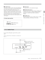
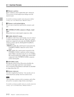
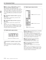
Chapter 2 Location and Function of Parts 8 Tape transport control section 1 PREROLL button PREROLL REW PLAY STANDBY 2 STANDBY button F FWD STOP 3 STOP button 4 F FWD button 5 PLAY button 6 SERVO indicator 7 REW button 1 PREROLL button Press this button to cue up to the preroll point (before the IN point by the time set as the preroll time) on the tape. You can change or select the preroll time and the state of the unit at the end of preroll ("stop mode" 1) or still playback mode) using setup menu item 001 or 401. Fault display function The STOP button flashes in the following cases: • When setup menu item 105 is set to ON, there is no external reference signal input. • The input external reference signal is different from the signal specified by setup menu item 337. 4 F FWD (fast forward) button To fast forward the tape, press this button, turning it on. 5 PLAY button To start playback, press this button, turning it on. To operate in capstan override mode Hold down this button, and turn the search dial. For details of capstan override mode, see page 4-4. 6 SERVO indicator Lights when the drum servo and capstan servo are locked. 7 REW (rewind) button To rewind the tape, press this button, turning it on. Cuing up to DMC playback control points Hold down the STUNT IN, STUNT OUT, PLAY IN, or PLAY OUT button while pressing this button to cue up to the corresponding DMC playback control point. 2 STANDBY button When this button is off with a cassette inserted in the unit, to put the unit in standby mode, press the button, turning it on. In standby mode, the drum is rotating and the tape is in contact with the drum. As a result, playback can start immediately. To end standby mode, press the STANDBY button, turning it off. If 8 minutes (value can be varied using setup menu item 501) elapse in standby mode, the unit automatically switches out of standby mode to protect the tape. 3 STOP button To stop playback, press this button, turning it on. 9 ALARM indicator and KEY INHI indicator ALARM indicator This lights when a hardware error is detected on the unit, and goes off when the error is resolved. When this indicator is lit, an error message appears in the time data/menu display section. If you are using the HDSDI OUTPUT 3 (SUPER), SDI OUTPUT 3 (SUPER) or COMPOSITE VIDEO OUTPUT 3 (SUPER) connector, then when the setting of F4 (CHARA) in function menu page 4 is ON, the error message also appears on the monitor screen. For details on error messages, refer to Section 1-24 in the Maintenance Manual Volume 1. KEY INHI (inhibit) indicator This indicator lights when the KEY INHI switch on the switch panel (see page 2-11) is set to ON. ...1) Stop mode: The state in which the device currently the subject of operation is stopped, and the STOP button is lit. 2-9 Chapter 2 Location and Function of Parts
-
 1
1 -
2
-
3
-
4
-
5
-
6
-
7
-
8
-
9
-
10
-
11
-
 12
12 -
 13
13 -
 14
14 -
 15
15 -
 16
16 -
 17
17 -
 18
18 -
 19
19 -
 20
20 -
 21
21 -
 22
22 -
23
-
24
-
25
-
26
-
27
-
28
-
29
-
30
-
31
-
32
-
33
-
34
-
35
-
36
-
37
-
38
-
39
-
40
-
41
-
42
-
43
-
44
-
45
-
46
-
47
-
48
-
49
-
50
-
51
-
52
-
53
-
54
-
55
-
56
-
57
-
58
-
59
-
60
-
61
-
62
-
63
-
64
-
65
-
66
-
67
-
68
-
69
-
70
-
71
-
72
-
73
-
74
-
75
-
76
-
77
-
78
-
79
-
80
-
81
-
82
-
83
-
84
-
85
-
86
-
87
-
88
-
89
-
90
-
91
-
92
-
93
-
94
-
95
-
96
-
97
-
98
-
99
-
100
-
101
-
102
-
103
-
104
-
105
-
106
-
107
-
108
-
109
-
110
-
111
-
112
-
113
-
114
-
115
 |
 |
