Sony HDWM2100/20 Operation Manual - Page 21
Connector Panel
 |
View all Sony HDWM2100/20 manuals
Add to My Manuals
Save this manual to your list of manuals |
Page 21 highlights
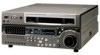
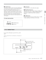
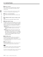
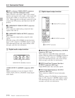
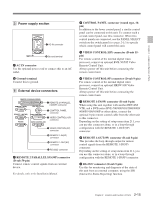
Chapter 2 Location and Function of Parts 2-2 Connector Panel Cooling fan 1 Analog audio output section 2 Analog video input/output section 3 Digital audio output section (see page 2-14) 75Ω 4 Digital signal output section (see page 2-14) Cooling fan 5 Power supply section (see page 2-15) 7 Time code output section (see page 2-16) 8 Audio monitor signal output section (see page 2-16) 6 External device connectors (see page 2-15) 1 Analog audio output section 1 AUDIO OUTPUT CH1 to CH4 connectors CH1 AUDIO OUTPUT CH2 CH3 CH4 CUE OUT 2 Analog video input/output section REF INPUT INPUT 1125/525 OFF ON 75Ω 1 REF.VIDEO INPUT connectors and 75Ω termination switch 2 CUE OUT connector 1 AUDIO OUTPUT CH1 to CH4 (channels 1 to 4) connectors (XLR 3-pin, male) These connectors output analog audio signals for channels 1 to 4. 2 CUE OUT (cue audio output) connector (XLR 3-pin, male) This connector outputs the analog cue audio signals. VIDEO OUTPUT COMPOSITE COMPONENT 1 Y 2 R-Y 3 (SUPER) B-Y 2 COMPONENT VIDEO OUTPUT connectors 3 COMPOSITE VIDEO OUTPUT connectors 2-13 Chapter 2 Location and Function of Parts
-
 1
1 -
2
-
3
-
4
-
5
-
6
-
7
-
8
-
9
-
10
-
11
-
12
-
13
-
14
-
15
-
 16
16 -
 17
17 -
 18
18 -
 19
19 -
 20
20 -
 21
21 -
 22
22 -
 23
23 -
 24
24 -
 25
25 -
 26
26 -
27
-
28
-
29
-
30
-
31
-
32
-
33
-
34
-
35
-
36
-
37
-
38
-
39
-
40
-
41
-
42
-
43
-
44
-
45
-
46
-
47
-
48
-
49
-
50
-
51
-
52
-
53
-
54
-
55
-
56
-
57
-
58
-
59
-
60
-
61
-
62
-
63
-
64
-
65
-
66
-
67
-
68
-
69
-
70
-
71
-
72
-
73
-
74
-
75
-
76
-
77
-
78
-
79
-
80
-
81
-
82
-
83
-
84
-
85
-
86
-
87
-
88
-
89
-
90
-
91
-
92
-
93
-
94
-
95
-
96
-
97
-
98
-
99
-
100
-
101
-
102
-
103
-
104
-
105
-
106
-
107
-
108
-
109
-
110
-
111
-
112
-
113
-
114
-
115
 |
 |
