Sony HDWM2100/20 Operation Manual - Page 23
Power supply External device connectors, REMOTE 2 PARALLEL I/O50P connector
 |
View all Sony HDWM2100/20 manuals
Add to My Manuals
Save this manual to your list of manuals |
Page 23 highlights
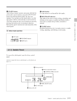
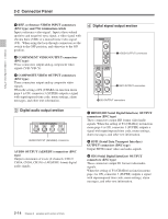
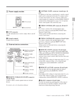
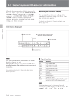
Chapter 2 Location and Function of Parts 5 Power supply section 1 AC IN connector 2 Ground terminal 1 AC IN connector Use the optional power cord to connect this to an AC outlet. 2 Ground terminal Connect this to ground. 6 External device connectors REMOTE 2 PARALLEL I/O(50P) REMOTE 1-IN(9P) CONTROL PANEL 1 REMOTE 2 PARALLEL I/O(50P) connector REMOTE 1-OUT(9P) RS232C 2 CONTROL PANEL VIDEO CONTROL (15P) connector 3 VIDEO CONTROL(15P) connector VIDEO CONTROL (9P) 4 VIDEO CONTROL(9P) connector 5 REMOTE 1-IN(9P) connector 6 REMOTE 1-OUT(9P) connector 7 RS-232C connector 1 REMOTE 2 PARALLEL I/O(50P) connector (D-sub 50-pin) Connect remote control signals from an external device. For details, refer to the Installation Manual. 2 CONTROL PANEL connector (round type, 10pin) In addition to the lower control panel, a similar control panel can be connected to this unit. To connect such a second control panel, use this connector. When two control panels are connected, use the PANEL SELECT switch on the switch panel (see page 2-11) to specify which control panel will control this unit. 3 VIDEO CONTROL(15P) connector (D-sub 15pin) For remote control of the internal digital video processor, connect an optional BVR-50/50P Video Remote Control Unit. Always power off this unit before connecting the remote control unit. 4 VIDEO CONTROL(9P) connector (D-sub 9-pin) For remote control of the internal digital video processor, connect an optional HKDV-900 Video Remote Control Unit. Always power off this unit before connecting the remote control unit. 5 REMOTE 1-IN(9P) connector (D-sub 9-pin) When using this unit together with another HDCAM VTR, and a BVE-series BVE-700/900/910/2000/9000/ 9000P/9100/9100P or other editor, connect the optional 9-pin remote control cable from the other unit to this connector. Depending on the setting of setup menu item 211, you can use this connector alone, or in a loop-through configuration with the REMOTE 1-OUT(9P) connector. 6 REMOTE 1-OUT(9P) connector (D-sub 9-pin) This provides the loop-through output for remote control signals from the REMOTE 1-IN(9P) connector. Depending on the setting of setup menu item 211, you can use this connector alone, or in a loop-through configuration with the REMOTE 1-IN(9P) connector. 7 RS-232C connector (D-sub 9-pin) Use this for monitoring and diagnosis of the state of this unit from an external computer, using the ISR (Interactive Status Reporting) function. 2-15 Chapter 2 Location and Function of Parts
-
 1
1 -
2
-
3
-
4
-
5
-
6
-
7
-
8
-
9
-
10
-
11
-
12
-
13
-
14
-
15
-
16
-
17
-
 18
18 -
 19
19 -
 20
20 -
 21
21 -
 22
22 -
 23
23 -
 24
24 -
 25
25 -
 26
26 -
 27
27 -
 28
28 -
29
-
30
-
31
-
32
-
33
-
34
-
35
-
36
-
37
-
38
-
39
-
40
-
41
-
42
-
43
-
44
-
45
-
46
-
47
-
48
-
49
-
50
-
51
-
52
-
53
-
54
-
55
-
56
-
57
-
58
-
59
-
60
-
61
-
62
-
63
-
64
-
65
-
66
-
67
-
68
-
69
-
70
-
71
-
72
-
73
-
74
-
75
-
76
-
77
-
78
-
79
-
80
-
81
-
82
-
83
-
84
-
85
-
86
-
87
-
88
-
89
-
90
-
91
-
92
-
93
-
94
-
95
-
96
-
97
-
98
-
99
-
100
-
101
-
102
-
103
-
104
-
105
-
106
-
107
-
108
-
109
-
110
-
111
-
112
-
113
-
114
-
115
 |
 |
