Sony KDF-E42A11E Operating Instructions - Page 19
Viewing pictures from, connected equipment, Navigating through, menus - hdmi
 |
View all Sony KDF-E42A11E manuals
Add to My Manuals
Save this manual to your list of manuals |
Page 19 highlights
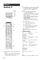
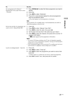
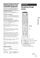
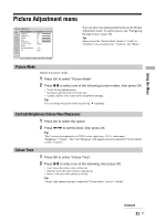
Viewing pictures from connected equipment Switch on the connected equipment, then perform one of the following operation. For equipment connected to the scart sockets using a fully-wired 21-pin scart lead Start playback on the connected equipment. The picture from the connected equipment appears on the screen. For an auto-tuned VCR page 11 Press PROG +/-, or the number buttons, to select the video channel. You can also press / repeatedly until the correct input symbol (see below) appears on the screen. For other connected equipment Press / repeatedly until the correct input symbol (see below) appears on the screen or press OK to access the Input signal index table. Press , to select an input source, press m/M, then press OK. 1/ 1, 2/ 2: Audio/video or RGB input signal through the scart socket / 1 or 2. appears only if an RGB source has been connected. 3: Component input signal through the Y, PB/CB, PR/CR sockets / 3, and audio input signal through the L/G/S/I, R/D/D/D sockets / 3. 4/ 4: Video input signal through the video socket 4, and audio input signal through the audio socket L/G/S/I (MONO), R/D/D/D sockets 4. appears only if the equipment is connected to the S video socket 4 instead of the video socket 4, and S video input signal is input through the S video socket 4. 5: RGB input signal through the PC connectors audio input signal through the socket 5. 5, and 6: Digital audio/video signal is input through the HDMI IN 6 socket. Audio input signal is analogue only if the equipment has been connected using the DVI and audio out socket. Additional operations To Do this Return to the normal Press DIGITAL or ANALOG. TV operation Access the Input signal index table Press OK. Press , to select an input source, press m/M, then press OK. Using the Menu Navigating through menus 2,3,4 4 1 1 Press MENU to display the menu. 2 Press M/m to select a menu icon, press ,. 3 Press M/m/
-
 1
1 -
2
-
3
-
4
-
5
-
6
-
7
-
8
-
9
-
10
-
11
-
12
-
13
-
 14
14 -
 15
15 -
 16
16 -
 17
17 -
 18
18 -
 19
19 -
 20
20 -
 21
21 -
 22
22 -
 23
23 -
 24
24 -
25
-
26
-
27
-
28
-
29
-
30
-
31
-
32
-
33
-
34
-
35
-
36
-
37
-
38
-
39
-
40
-
41
-
42
-
43
-
44
-
45
-
46
-
47
-
48
-
49
-
50
-
51
-
52
-
53
-
54
-
55
-
56
-
57
-
58
-
59
-
60
-
61
-
62
-
63
-
64
-
65
-
66
-
67
-
68
-
69
-
70
-
71
-
72
-
73
-
74
-
75
-
76
-
77
-
78
-
79
-
80
-
81
-
82
-
83
-
84
-
85
-
86
-
87
-
88
-
89
-
90
-
91
-
92
-
93
-
94
-
95
-
96
-
97
-
98
-
99
-
100
-
101
-
102
-
103
-
104
-
105
-
106
-
107
-
108
-
109
-
110
-
111
-
112
-
113
-
114
-
115
-
116
-
117
-
118
-
119
-
120
-
121
-
122
-
123
-
124
-
125
-
126
-
127
-
128
-
129
-
130
-
131
-
132
-
133
-
134
-
135
-
136
-
137
-
138
-
139
-
140
-
141
-
142
-
143
-
144
-
145
-
146
-
147
-
148
-
149
-
150
-
151
-
152
-
153
-
154
-
155
-
156
-
157
-
158
-
159
-
160
-
161
-
162
-
163
-
164
-
165
-
166
-
167
-
168
-
169
-
170
-
171
-
172
-
173
-
174
-
175
-
176
-
177
-
178
-
179
-
180
-
181
-
182
-
183
-
184
-
185
-
186
-
187
-
188
-
189
 |
 |