Sony LF-B1 Operating Instructions (LF-PK1) - Page 5
Identifying Parts and Controls (Base Station - locationfree base station
 |
View all Sony LF-B1 manuals
Add to My Manuals
Save this manual to your list of manuals |
Page 5 highlights
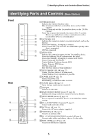
Identifying Parts and Controls (Base Station) Identifying Parts and Controls (Base Station) Front Rear qf qd qs 1 WIRELESS LED Indicates the wireless function status. Blue: Connected with the LocationFree device on the 5 GHz channel. Green: Connected with the LocationFree device on the 2.4 GHz channel. Turns blue or green momentarily, then turns off for 3 seconds: 1 Wireless is enabled, but wireless communication with a LocationFree device is not taking place. 2 2 NETWORK LED 3 Indicates the connection status to an external network, such as the Internet. 4 Green slow blinking: Attempting to connect. Green: Connected to the network. The LED blinks quickly when data is transmitted. Off: Not connected. 5 3 NETAV LED Indicates the connection status with the LocationFree device. 6 Green fast blinking: NetAV authentication has failed. Green slow blinking: Attempting to connect with NetAV. Green: Connected with NetAV. Umber blinking: Updating dynamic DNS. Umber: Dynamic DNS failure. Off: Not connected. Red: The base station is being initialized. 4 SETUP MODE LED (1 page 12) Umber: The base station is in Setup mode. Umber blinking: Easy registration is possible. 5 POWER LED (1 page 13) Green: The power is on. Red blinking: A malfunction has occurred. 6 POWER button (1 page 13) Turns the base station power on and off. 7 LAN port Connect a LAN cable. 8 BASE STATION RESET button (1 page 48) Initializes all settings on the base station to the factory defaults. 9 SETUP MODE button (1 page 12) Press to register LocationFree devices, or to make base station 7 settings. 8 0 IN 2 (AUDIO/VIDEO) terminal (1 page 9) Connect audio and video cables. 9 qa DC IN jack (1 page 13) Connect the AC power adapter (supplied). 0 qs VHF/UHF jack (1 page 7) Connect an antenna cable. qd IN 1 (S-VIDEO/AUDIO/VIDEO) terminal (1 page 9) Connect audio cables and either a video or S-video cable. qa qf IR BLASTER port (1 page 10) Connect the IR Blaster (supplied). 5
-
 1
1 -
 2
2 -
 3
3 -
 4
4 -
 5
5 -
 6
6 -
 7
7 -
 8
8 -
 9
9 -
 10
10 -
 11
11 -
12
-
13
-
14
-
15
-
16
-
17
-
18
-
19
-
20
-
21
-
22
-
23
-
24
-
25
-
26
-
27
-
28
-
29
-
30
-
31
-
32
-
33
-
34
-
35
-
36
-
37
-
38
-
39
-
40
-
41
-
42
-
43
-
44
-
45
-
46
-
47
-
48
-
49
-
50
-
51
-
52
-
53
-
54
-
55
-
56
-
57
-
58
-
59
 |
 |
