Toshiba T42F3F500XAMBN User Manual
Toshiba T42F3F500XAMBN Manual
 |
View all Toshiba T42F3F500XAMBN manuals
Add to My Manuals
Save this manual to your list of manuals |
Toshiba T42F3F500XAMBN manual content summary:
- Toshiba T42F3F500XAMBN | User Manual - Page 1
TOSHIBA UNINTERRUPTIBLE POWER SYSTEM THREE-PHASE 15/25/30/50 kVA UPS 4200FA CT/XT User's Manual Document Number: 53878-006 Date: September 2007 - Toshiba T42F3F500XAMBN | User Manual - Page 2
Batteries or External Transformer USER'S MANUAL FOR MODELS C42F3F150X#MBN C42F3F150F#MBN C42#3#150##MXN C42F3F250X#MBN C42F3F250F#MBN C42#3#250##MXN T42F3F300X#MBN T42F3F300F#MBN T42#3#300##MXN T42F3F500XAMBN T42F3F500F#MBN T42#3#500##MXN TOSHIBA INTERNATIONAL CORPORATION INDUSTRIAL DIVISION 13131 - Toshiba T42F3F500XAMBN | User Manual - Page 3
problems arise which are not covered sufficiently the matter should be referred to the local TOSHIBA sales office. The contents of this instruction manual assistance is required call TOSHIBA Customer Support Center toll free at 1- 877-876-8773, or write to: Toshiba International Corporation, 13131 - Toshiba T42F3F500XAMBN | User Manual - Page 4
CONTENTS IMPORTANT NOTICE...2 TABLE OF CONTENTS...3 Purpose and Scope of Manual 5 Contacting TOSHIBA Customer Support Center 5 GENERAL SAFETY INSTRUCTIONS 6 EQUIPMENT WARNING LABELS 7 IMPORTANT SAFETY INSTRUCTIONS 10 1.0 Product Description 14 1.1 Theory of Operation ...14 1.2 Application and - Toshiba T42F3F500XAMBN | User Manual - Page 5
TOSHIBA 6.0 Operating the UPS 37 6.1 AC Input Mode (Normal Operation 37 6.2 Bypass Mode...38 6.4 Battery Backup Mode ...39 6.5 Battery Backup Time 63 9.1 External Dimensions 15/25/30 kVA 63 9.2 External Dimensions 50kVA...64 9.3 Shipping Dimensions and Weights 65 4200FA CT/XT User's Manual 4 - Toshiba T42F3F500XAMBN | User Manual - Page 6
how to safely install, operate, and maintain your TOSHIBA power electronics product. This manual includes a section on General Safety Instructions that describes the warning labels and symbols that are used throughout the manual. Read the manual completely before installing, operating, or performing - Toshiba T42F3F500XAMBN | User Manual - Page 7
TOSHIBA GENERAL SAFETY INSTRUCTIONS DO NOT attempt to install, operate, maintain or dispose of this equipment until you have read and understood all of the product safety information and directions that are contained in this manual. Safety Alert Symbol The Safety Alert Symbol indicates that a - Toshiba T42F3F500XAMBN | User Manual - Page 8
and user directions that are contained in this instruction manual. Shown below are examples of warning labels that may be found attached to the equipment. DO NOT remove or cover any of the labels. If the labels are damaged or if additional labels are required, contact your TOSHIBA representative for - Toshiba T42F3F500XAMBN | User Manual - Page 9
TOSHIBA DANGER RISK OF ELECTRIC SHOCK Capacitors stay charged after power has good, safe operating condition. While servicing, stand on some type of insulation, and be sure not to be grounded. Follow the safety instructions given in the equipment manual carefully and observe all danger, warning - Toshiba T42F3F500XAMBN | User Manual - Page 10
TOSHIBA NOTE: This Label for Battery Units Only 4200FA CT/XT User's Manual 9 - Toshiba T42F3F500XAMBN | User Manual - Page 11
TOSHIBA IMPORTANT SAFETY INSTRUCTIONS SAVE THESE INSTRUCTIONS This manual contains important instructions that should servicing should be performed by a qualified TOSHIBA Representative only. 4. Unauthorized personnel should not service batteries. 5. Contact your nearest TOSHIBA authorized service - Toshiba T42F3F500XAMBN | User Manual - Page 12
models is 288 VDC. An Authorized TOSHIBA Representative who is knowledgeable of batteries and the required precautions should perform service on the batteries. Keep unauthorized personnel away from batteries. Refer to the Battery System Manual, when scheduling maintenance or battery replacement - Toshiba T42F3F500XAMBN | User Manual - Page 13
TOSHIBA The following precautions should be observed when working gravity of the electrolyte. The batteries are valve regulated lead acid type and such servicing is not possible without damaging the battery. 11) Use proper lifting means when or maintenance. 4200FA CT/XT User's Manual 12 - Toshiba T42F3F500XAMBN | User Manual - Page 14
TOSHIBA INSTRUCTIONS IMPORTANTES CONCERNANT LA SÉCURITÉ CONSERVER CES INSTRUCTIONS Cette notice contient des instructions importantes concernant la sécurté ATTENTION Un battery puet présenter un risque de choc électrique, de brûlure par transfert d' énergie. ATTENTION L'élimination des - Toshiba T42F3F500XAMBN | User Manual - Page 15
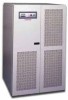
TOSHIBA 4200FA On-Line, Uninterruptible Power Systems (UPS) provide continuous computer personal computers to mini-computers to supports the load equipment, without interruption. For example, when used to support a computer , everyday problems associated with keep power-line problems from reaching your - Toshiba T42F3F500XAMBN | User Manual - Page 16
TOSHIBA 2.0 Unpacking/Inspection/Storage/Disposal 2.1 Unpacking the new UPS equipment 15/25/30 kVA: Upon receipt of the UPS, a careful inspection for shipping ONLY WITH ADEQUATE EQUIPMENT AND TRAINED PERSONNEL. THIS EQUIPMENT WILL TIP OVER EASILY UNTIL FIXED IN PLACE. 4200FA CT/XT User's Manual 15 - Toshiba T42F3F500XAMBN | User Manual - Page 17
TOSHIBA 2.2 Unpacking the new UPS equipment 50 kVA: Upon receipt of the UPS, a careful inspection for shipping damage should be made. Units shipped within AND ONLY WITH ADEQUATE EQUIPMENT AND TRAINED PERSONNEL. THIS EQUIPMENT WILL TIP OVER EASILY UNTIL FIXED IN PLACE. 4200FA CT/XT User's Manual 16 - Toshiba T42F3F500XAMBN | User Manual - Page 18
the system's batteries. 2) Perform a complete system shutdown as described in section 6.15 of this manual. Storing: 1) Store within a temperature range of - 4 - 104 °F (-20 - 40 in your area, the battery manufacturer, or call TOSHIBA toll-free at (877) 867-8773 for more information about recycling batteries. - Toshiba T42F3F500XAMBN | User Manual - Page 19
TOSHIBA 3.0 Installation Precautions Based on the 4200FA to high humidity. Also, do not install the unit in areas that are exposed to direct sunlight, or contaminated areas subject to high levels of airborne dust, metal particles, or flammable the affected equipment. 4200FA CT/XT User's Manual 18 - Toshiba T42F3F500XAMBN | User Manual - Page 20
Precautions 1) The UPS should not be powered up until the entire User's Manual has been reviewed, and understood. 2) The input power source voltage must not attempt to disassemble, modify, or repair the UPS. Call TOSHIBA Service for repair information. 9) Turn the power on only after attaching ALL - Toshiba T42F3F500XAMBN | User Manual - Page 21
TOSHIBA 13) Additional warnings and notifications shall be posted at the equipment installation location as deemed required by Qualified Personnel. CAUTION Input: 3-phase, 3-Wire *208 V requires 3-phase, TB4 4-Wire Wye INPUT GROUND RESISTANCE LESS THAN 10 OHMS 4200FA CT/XT User's Manual 20 - Toshiba T42F3F500XAMBN | User Manual - Page 22
TOSHIBA 4.1.2 Power Connections 15/25/30 kVA with Internal Transformer The following illustrates the wiring connections from the power distribution panel ( RESISTANCE LESS THAN 10 OHMS Optional Bypass Input: 3-Phase, 3-Wire *208 V requires 3-Phase, TB4 4-Wire Wye 4200FA CT/XT User's Manual 21 - Toshiba T42F3F500XAMBN | User Manual - Page 23
TOSHIBA 4.1.3 Recommended Wire Size and Torque Requirements UPS Input and Output Terminals Minimum Wire Size and Torque Requirements UPS Input and Output Terminals 15/25/30 6 51 in-lbs. 600 V 10 35 in-lbs. 10 35 in-lbs. 10 35 in-lbs. Maximum Wire Size is 2 AWG. 4200FA CT/XT User's Manual 22 - Toshiba T42F3F500XAMBN | User Manual - Page 24
TOSHIBA 4.1.4 Power Connection Cable Routing and Conduit Placement 15/25/30 kVA The following illustrates the proper cable routing that should be Authority having jurisdiction. Battery conductors shall be installed in a separate conduit and be of low resistance type. 4200FA CT/XT User's Manual 23 - Toshiba T42F3F500XAMBN | User Manual - Page 25
TOSHIBA 4.2 Control Circuit and External Battery Interface Connections 15/25/30 kvA The following illustrates the wiring connections of the Control Circuits, and Battery are to be used. Maximum Wire Size for Control Circuits is 12 AWG. Maximum for Battery is 2 AWG. 4200FA CT/XT User's Manual 24 - Toshiba T42F3F500XAMBN | User Manual - Page 26
TOSHIBA 4.3 Power Connections 50 kVA The following illustrates the wiring connections from the power distribution panel (not part of the wire OUTPUT: 3-phase (4-wire) TB1 (H1) (H2) (H3) (N) Optional: Bypass Input: 3-phase, 3-wire 208 V requires 3-phase, 4-wire TB4 4200FA CT/XT User's Manual 25 - Toshiba T42F3F500XAMBN | User Manual - Page 27
TOSHIBA 4.3.1 Recommended Wire Size and Torque Requirements For UPS Input and Output Terminals (H1) (H2) (H3) 208 V 220 V 240 V 380 V 400 V 415 V 480 V -lbs. 600 V 6 N/A 200 in-lbs. Maximum Wire Size for Input is 1/0 AWG. Maximum Wire Size for Neutral is 250MCM. 4200FA CT/XT User's Manual 26 - Toshiba T42F3F500XAMBN | User Manual - Page 28
TOSHIBA 4.3.2 Power Connection Cable Routing and Conduit Placement 50 kVA The following illustrates the proper cable routing that should be followed during the power connection process for the 50kVA. Removable cover for conduit access Bottom Conduit Entry 4200FA CT/XT User's Manual 27 - Toshiba T42F3F500XAMBN | User Manual - Page 29
TOSHIBA 4.4 Control Circuit and External Interface Connections 50 kVA The following illustrates the wiring connections of the Control Circuits, and Battery Interface 14-16 8 in-lbs. *Indicates Class 1 wiring methods are to be used. Maximum Wire Size is 12 AWG. 4200FA CT/XT User's Manual 28 - Toshiba T42F3F500XAMBN | User Manual - Page 30
TOSHIBA 4.5 4.5.1 Communication Interface Remote Contact This interface is a standard feature and is available as dry switch contacts through a DB9 male connector Common). 2) Contacts are rated at 30 VDC, 0.1 amps; 125 VAC, 3 amps. 3) Pin number "3" is not used. 4200FA CT/XT User's Manual 29 - Toshiba T42F3F500XAMBN | User Manual - Page 31
of the UPS from a computer network running TOSHIBA RemotEyeII™ software. The computer and the UPS are connected internal batteries, a 'shutdown' order can be sent to the UPS instructing it to turn OFF after a user-specified amount of time. directions listed on the RS-232C screen. 4200FA CT/XT User - Toshiba T42F3F500XAMBN | User Manual - Page 32
TOSHIBA 5.0 Specifications 5.1 4200FA 15 / 25 kVA @ 208 VAC Input/ 208 VAC Output w/ 0.8 lagging 3 phase ; 4 Wire + GND ± 2% (0-100% balanced load); ± 3% (0-100% unbalanced load) ± 5V Manually from the key pad ± 2° (0-100% balanced load); ± 4° (unbalanced load) 50 / 60 Hz ± 0.1% in free - Toshiba T42F3F500XAMBN | User Manual - Page 33
TOSHIBA 5.2 4200FA 15/25 kVA w/Internal Transformer Input Battery Output Environment Model Number 5.5% 288 VDC (216 - 332 VDC) 324.0 VDC (± 2%) 0.5 V R.M.S. Refer to Battery System Manual 10.0 Amps (Determined by Output Transformer internal to the unit) VA / Nominal Output Voltage / 1.73 - Toshiba T42F3F500XAMBN | User Manual - Page 34
TOSHIBA 5.3 4200FA 30 kVA @ 208 VAC Input/ 208 VAC Output w/Internal Batteries Amps 0.8 lagging 3 phase ; 4 Wire + GND ± 2% (0-100% balanced load); ± 3% (0-100% unbalanced load) ± 5V Manually from the key pad ± 2° (0-100% balanced load); ± 4° (unbalanced load) 50 / 60 Hz ± 0.1% in free running - Toshiba T42F3F500XAMBN | User Manual - Page 35
TOSHIBA 5.4 4200FA 30 kVA w/Internal Transformer Input Battery Output Environment Model Number 3% THD 288 VDC (216 to 332 VDC) 324.0 VDC (± 2%) 0.5 V R.M.S. Refer to Battery System Manual 10.0 Amps (Determined by Output Transformer internal to the unit) VA / Nominal Output Voltage / 1.73 0.8 - Toshiba T42F3F500XAMBN | User Manual - Page 36
TOSHIBA be removed Audible Noise Operating Temperature Operating Humidity Altitude *** T42F3F500XAMBN T42F3F500##MBN 50 kVA 35.5" X 38.3" X 59 Wire + GND ± 2% (0-100% balanced load); ± 3% (0-100% unbalanced load) ± 5V Manually from key pad ± 2° (0-100% balanced load); ± 4° (unbalanced load) 50 / 60 - Toshiba T42F3F500XAMBN | User Manual - Page 37
TOSHIBA 5.6 4200FA 50kVA w/Internal Transformer Input Battery Output Environment Model Number Input 3% THD 288 VDC (216 to 332 VDC) 324.0 VDC (± 2%) 0.5 V R.M.S. Refer to Battery System Manual 11.5 Amps (Determined by Output Transformer internal to the unit) VA / Nominal Output Voltage / 1.73 0.8 - Toshiba T42F3F500XAMBN | User Manual - Page 38
TOSHIBA 6.0 Operating the UPS 6.1 AC Input Mode (Normal Operation) The following illustration shows circuit power flow when the UPS is operating MCCB MBS Bypass Converter Inverter Output Power Charger/ Chopper External Batteries Power flow in AC Input Mode 4200FA CT/XT User's Manual 37 - Toshiba T42F3F500XAMBN | User Manual - Page 39
TOSHIBA 6.2 Bypass Mode If the UPS unit is severely overloaded or develops an flow is transferred to the Bypass circuit due to a fault condition, then the power flow must be transferred manually from the UPS's Bypass circuit back to the Inverter circuit after repairing the fault (see "Start-up - Toshiba T42F3F500XAMBN | User Manual - Page 40
TOSHIBA 6.4 Battery Backup Mode The following illustration shows power flow during the battery backup mode. When commercial AC power failures XFMR MCCB Bypass Converter Inverter Charger/ Chopper External Batteries Power flow in battery backup mode Output Power 4200FA CT/XT User's Manual 39 - Toshiba T42F3F500XAMBN | User Manual - Page 41
6.5 Battery Backup Time and Discharge Process The UPS system, when used in conjunction with a TOSHIBA designed Battery System, is designed to provide several minutes of back-up time (Refer to the Battery System Manual for back-up times). These times are valid when the unit is operating under full - Toshiba T42F3F500XAMBN | User Manual - Page 42
TOSHIBA 6.7 Battery Recharging The illustration below shows a graphical representation of the UPS battery recharge process after a full discharge. The recharge process Transformer 324.0 VDC 324 VDC 324 VDC 216 VDC 216 VDC 216 VDC 4.0 A 10.0 A 11.5 Amps 4200FA CT/XT User's Manual 41 - Toshiba T42F3F500XAMBN | User Manual - Page 43
TOSHIBA 6.8 Front Panel Layout (All Units) Refer to the following illustration for the entire UPS front panel operating procedures. 44-l- XFMR MBS TRIPPED MCCB OFF Converter Bypass OFF Charger/ Chopper OFF Inverter Output Power External Batteries 4200FA CT/XT User's Manual 42 - Toshiba T42F3F500XAMBN | User Manual - Page 44
TOSHIBA 6.10 Audible Alarm Functions Audible alarms will sound when the UPS is in the Battery Backup Mode, has a fault, is at the low battery if the battery voltage reaches the shutdown level during the battery-discharge mode. On when the UPS is experiencing a fault. 4200FA CT/XT User's Manual 43 - Toshiba T42F3F500XAMBN | User Manual - Page 45
TOSHIBA 6.11.1 LED (Light Emitting Diode) System Status The following chart shows the UPS system status that can be determined by decoding the " Shutdown Sequence of the Inverter and Bypass is not available. - BATTERY BACKUP - Displayed during input power failure. 4200FA CT/XT User's Manual 44 - Toshiba T42F3F500XAMBN | User Manual - Page 46
TOSHIBA 6.12.2 Line-2 System Fault Messages Line-2 fault messages System Messages Line-3 messages show load current information, and user selected instructions. 6.12.4 Line-4 System Messages Line-4 messages reflect the UPS operating Faults have occurred. (Abnormal) 4200FA CT/XT User's Manual 45 - Toshiba T42F3F500XAMBN | User Manual - Page 47
TOSHIBA Note: 1) Line-4 will be blank when the BATT key is pressed during Battery Backup Mode with normal battery voltage. 2) The # the Circuit Breaker to "off." 3) Repeat Initial Battery Charge procedure. (A failure indicates battery replacement may be necessary). 4200FA CT/XT User's Manual 46 - Toshiba T42F3F500XAMBN | User Manual - Page 48
TOSHIBA 6.14 Start-up Procedure The UPS batteries must be charged before the UPS is used for the first time or if the unit has not FAULT (BYPASS ON) (DESCRIPTION) PRESS DOWN TO DETAIL > ENTER FOR DETAILS Refer to the "Line-2 System Fault Messages" section for details. 4200FA CT/XT User's Manual 47 - Toshiba T42F3F500XAMBN | User Manual - Page 49
TOSHIBA 6.15 Shutdown Procedure When turning off the UPS, the following shutdown procedure should Bypass, the following operation procedure should be used: WARNING Failure to adhere to the following instructions could result in damage to your equipment and/or you risk removal of power to any - Toshiba T42F3F500XAMBN | User Manual - Page 50
TOSHIBA 6.16.1 From UPS to Maintenance Bypass 1) Move the labeled "MAIN POWER SWITCH." The unit is now in the Maintenance Bypass mode and may be serviced. For units with internal transformers, the transformers are still energized. 6.16.2 From Maintenance Bypass load. 4200FA CT/XT User's Manual 49 - Toshiba T42F3F500XAMBN | User Manual - Page 51
TOSHIBA 6.17 Keypad Overview The following illustrates the 12-key data entry pad with each key functionally labeled. MONI BATT F1 IN OUT BATT data values or to forward through menus. Press to reverse through display data values or to reverse through menus. 4200FA CT/XT User's Manual 50 - Toshiba T42F3F500XAMBN | User Manual - Page 52
TOSHIBA 6.18 Key Functions 6.18.1 MONI After the UPS Display Duration"). All system 'line' messages will be displayed from MONI mode when abnormal operating problems are detected. If AC input power is available and the UPS is operating normally, the the "up/down" keys. 4200FA CT/XT User's Manual 51 - Toshiba T42F3F500XAMBN | User Manual - Page 53
TOSHIBA 6.18.4 BATT Key When the BATT key is pressed during normal 'AC Input Mode' of operation, the LCD screen displays details about the and to display the following screen while batteries are tested: - BATTERY TEST BATTERY VOLTAGE=324V ## MINS ## SECS > PLEASE WAIT 4200FA CT/XT User's Manual 52 - Toshiba T42F3F500XAMBN | User Manual - Page 54
TOSHIBA When the battery test is completed, the previous operation will be resumed and the main system MONI screen will be displayed. If the battery is successful then the display will begin from the 'Start-up screen' and then change to the 'main monitor' screen. 4200FA CT/XT User's Manual 53 - Toshiba T42F3F500XAMBN | User Manual - Page 55
TOSHIBA 6.19 Menu Data Screens 6.19.1 Settings for Calendar and Clock Press the MENU key to access the menu data screens and press the 'down' arrow MIN >F1: DATA SET MODE >Δ/∇:PRV/NEXT SCREEN Press the F1 key to display the LCD-Idle mode setting adjustment screen: 4200FA CT/XT User's Manual 54 - Toshiba T42F3F500XAMBN | User Manual - Page 56
TOSHIBA DISPLAY DURATION SET 30 MIN >Δ/∇: CHANGE DATA >ENTER:ACCEPT CHANGE Press the 'up' or 'down' arrow key to move the display the following active adjustment screen: SER COM STATION ADDR STATION ADDRESS: 31H >Δ/∇: CHANGE DATA >ENTER: ACCEPT CHANGE 4200FA CT/XT User's Manual 55 - Toshiba T42F3F500XAMBN | User Manual - Page 57
TOSHIBA 6.19.6 Output Voltage Adjustment When the MENU key is pressed and held 3-4 the F1 key will have no effect on this display screen 6.19.7 Equalize Charge Mode Select Contact Toshiba Customer Support toll free at 1-877-867-8773 before using this option. DAMAGE to the battery system may occur - Toshiba T42F3F500XAMBN | User Manual - Page 58
TOSHIBA 6.19.8 Reset to Default Settings Press the MENU key to access the menu data screens and press the 'down' arrow key to scroll to present, the following screen will be displayed: - BYPASS OPERATION OUTPUT VOLTAGE=208 CURRENT= 114/116/114% * UPS OL: REDUCE LOAD * 4200FA CT/XT User's Manual 57 - Toshiba T42F3F500XAMBN | User Manual - Page 59
TOSHIBA After the load is reduced, if the STOP/RUN key switch is in the RUN position, the UPS will automatically return to 'Inverter Operation' the record relating to the first discharge event. BACKUP HISTORY ( 1) #MIN##SEC VB=324V BT *PF OL >Δ/∇: EXIT F1: NEXT 4200FA CT/XT User's Manual 58 - Toshiba T42F3F500XAMBN | User Manual - Page 60
TOSHIBA Press the F1 key again to display the record relating to each subsequent discharge event. BACKUP HISTORY ( #) #MIN##SEC VB=324V BT *PF OL or 'down' arrow keys to return to the Fault Count screen. TOTAL FAULT COUNT ## TIMES > F1: FOR DETAILS >Δ/∇: TO SCROLL 4200FA CT/XT User's Manual 59 - Toshiba T42F3F500XAMBN | User Manual - Page 61
TOSHIBA 7.0 UPS Protection System 7.1 System Protection Features The preceding one-line schematic illustrates the electrical locations of the protection devices on all Battery Lamp Flickers NO NO Low Battery Relay closed Bypass Relay closed No Yes, if bypass ok 4200FA CT/XT User's Manual 60 - Toshiba T42F3F500XAMBN | User Manual - Page 62
with and follow the important safety instructions within this manual. WARNING Proper maintenance of the battery system of this unit by a qualified service technician is essential to the safety and reliability of your UPS system. Schedule authorized TOSHIBA service centers to perform internal parts - Toshiba T42F3F500XAMBN | User Manual - Page 63
TOSHIBA 8.3 Parts Replacement The following list shows intervals for periodic maintenance and replacement of certain UPS parts. 1) Batteries: VRLA : Replace once every 5 years. 3) Fuses: Replace once every 7 years. 4) Cooling fan: Replace once every 3 years. 4200FA CT/XT User's Manual 62 - Toshiba T42F3F500XAMBN | User Manual - Page 64
TOSHIBA 9.0 External Dimensions / Shipping Dimensions / Weights 9.1 External Dimensions 15/25/30 kVA 20.0 in. (508 mm) 59.7 in. (1516 mm) 56.0 in. (1422 mm) 36.3 in. (922 mm) 4200FA CT/XT User's Manual 63 - Toshiba T42F3F500XAMBN | User Manual - Page 65
TOSHIBA 9.2 External Dimensions 50kVA 35.5 in. (901 mm) 59.3 in. (1506 mm) 38.3 in. (972 mm) 4200FA CT/XT User's Manual 64 - Toshiba T42F3F500XAMBN | User Manual - Page 66
TOSHIBA 9.3 Shipping Dimensions and Weights All 15, 25 & 30 kVA models Width Depth Height Height with packing material Shipping Dimensions, Standard Inches (cm) 50 kVA with 2 internal transformers 1800 (816) 1700 (771) 2050 (930) 1900 (862) 1800 (816) 2150 (975) 4200FA CT/XT User's Manual 65 - Toshiba T42F3F500XAMBN | User Manual - Page 67
- Toshiba T42F3F500XAMBN | User Manual - Page 68
INDUSTRIAL DIVISION 13131 West Little York Rd., Houston, TX 77041 Tel: 713/466-0277 Fax 713/466-8773 US 877/867-8773 Canada 800/872-2192 Mexico 01/800/527-1204 www.toshiba.com/ind Printed in the U.S.A.
-
 1
1 -
 2
2 -
 3
3 -
 4
4 -
 5
5 -
 6
6 -
 7
7 -
8
-
9
-
10
-
11
-
12
-
13
-
14
-
15
-
16
-
17
-
18
-
19
-
20
-
21
-
22
-
23
-
24
-
25
-
26
-
27
-
28
-
29
-
30
-
31
-
32
-
33
-
34
-
35
-
36
-
37
-
38
-
39
-
40
-
41
-
42
-
43
-
44
-
45
-
46
-
47
-
48
-
49
-
50
-
51
-
52
-
53
-
54
-
55
-
56
-
57
-
58
-
59
-
60
-
61
-
62
-
63
-
64
-
65
-
66
-
67
-
68
 |
 |
TOSHIBA
U
NINTERRUPTIBLE
P
OWER
S
YSTEM
THREE-PHASE 15/25/30/50 kVA UPS
4200
FA CT/XT
User’s Manual
Document Number: 53878-006
Date: September 2007