Toshiba T42F3F500XAMBN User Manual - Page 36
kVA @ 208 VAC Input/ 208 VAC Output w/Internal Batteries
 |
View all Toshiba T42F3F500XAMBN manuals
Add to My Manuals
Save this manual to your list of manuals |
Page 36 highlights
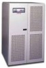
TOSHIBA 5.5 4200FA 50kVA @ 208 VAC Input/ 208 VAC Output w/Internal Batteries Input Battery Output Environment Model Number Rated Output Capacity External Dimensions W x D x H (cm) Rated Voltage Voltage Variation Rated Frequency Input Cables Required Dual Input Option Cables required * Power Factor Required Input kVA Walk-in Function Inrush Current Current Limit * Harmonic Currents DC Nominal (Voltage Range) Float Charge (Regulation) Ripple Voltage **Rated Back-up Time Rated Charge Current Rated Voltage Rated Current Rated Power Factor Output Cables Required Voltage Regulation (phase-phase) Voltage Adjustment Range Phase Displacement Rated Frequency Frequency Regulation Frequency Synchronous Frequency Slew Rate Voltage Transients (Recovery time: 50 ms) Inverter Overload Capacity Bypass Overload Capacity Crest Factor Neutral Line Conductor Harmonic Voltage Distortion Inrush Current protection Efficiency (Typical) Heat loss to be removed Audible Noise Operating Temperature Operating Humidity Altitude *** T42F3F500XAMBN T42F3F500##MBN 50 kVA 35.5" X 38.3" X 59.3" (90.1 cm x 97.2 cm x 150.6 cm) 208 VAC +10% to -30%; (-15% to -30%) **** 50 / 60 Hz 3 phase ; 4 Wire + GND 3 phase ; 4 Wire + GND Greater than 0.98 when in inverter mode 46 kVA From 20% to 100% over 5 seconds Less than 8 times the rated current under synchronous operation 115% maximum Less than 3% THD 288 VDC (216 to 332 VDC) 324.0 VDC (± 2%) 0.5 V R.M.S. 5 min. at full load 11.5 Amps 208 / 120 VAC 138.9 Amps 0.8 lagging 3 phase ; 4 Wire + GND ± 2% (0-100% balanced load); ± 3% (0-100% unbalanced load) ± 5V Manually from key pad ± 2° (0-100% balanced load); ± 4° (unbalanced load) 50 / 60 Hz ± 0.1% in free running mode ± 0.5/1.0/1.5 Hz (± 1.0 Hz. std.) switch selectable by qualified technician 1 Hz/s to 3Hz/s(in 0.5 Hz steps) ± 5% (100% load step change); ± 3% (loss or return of input voltage); ± 8% (transfer of bypass to inverter) 125% 90 sec; 150% 30 sec 1000% 10 ms; 125% 10 min. 2.5-3.0 within the kW range 1.73 (200%) times line rating 1.5% max (linear load) Automatic Transfer to bypass, then retransfer to inverter AC/DC/AC: 88%; DC/AC: 89% 17,611 BTU/hr (4,437 kcal/hr) ~65dB @ 1 meter from the front of the unit 32 - 104 °F (0 - 40 °C); optimal temperature is 77 °F (25 °C) 30-90% RH (non condensing) Less than 2000 meters Items marked with an (*) are specified at rated conditions under balanced linear loads. (**) Battery backup time may vary depending on the operating conditions and ambient temperature at the installation site, and an initial charge time of 24 hrs is necessary to obtain proper battery performance level before the unit is placed in operation. (***) At 6600-ft (2000 m) above sea level, output capacity should be derated by 3% (Consult Factory for higher elevations). (****) Prolonged operation at this level requires some derating of the output capacity. 4200FA CT/XT User's Manual 35
-
 1
1 -
2
-
3
-
4
-
5
-
6
-
7
-
8
-
9
-
10
-
11
-
12
-
13
-
14
-
15
-
16
-
17
-
18
-
19
-
20
-
21
-
22
-
23
-
24
-
25
-
26
-
27
-
28
-
29
-
30
-
 31
31 -
 32
32 -
 33
33 -
 34
34 -
 35
35 -
 36
36 -
 37
37 -
 38
38 -
 39
39 -
 40
40 -
 41
41 -
42
-
43
-
44
-
45
-
46
-
47
-
48
-
49
-
50
-
51
-
52
-
53
-
54
-
55
-
56
-
57
-
58
-
59
-
60
-
61
-
62
-
63
-
64
-
65
-
66
-
67
-
68
 |
 |
