Toshiba T42F3F500XAMBN User Manual - Page 24
Power Connection Cable Routing and Conduit Placement 15/25/30 kVA
 |
View all Toshiba T42F3F500XAMBN manuals
Add to My Manuals
Save this manual to your list of manuals |
Page 24 highlights
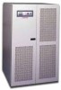
TOSHIBA 4.1.4 Power Connection Cable Routing and Conduit Placement 15/25/30 kVA The following illustrates the proper cable routing that should be followed during the power connection process of the 15/25/30 kVA. CONDUIT MOUNTING PANEL INPUT CONDUIT OUTPUT CONDUIT BATTERY CONDUIT Note: 1) 2) Input and Output conductors shall be installed in separate conduits, and installed in accordance with the latest edition of NEC and the Local Authority having jurisdiction. Battery conductors shall be installed in a separate conduit and be of low resistance type. 4200FA CT/XT User's Manual 23
-
 1
1 -
2
-
3
-
4
-
5
-
6
-
7
-
8
-
9
-
10
-
11
-
12
-
13
-
14
-
15
-
16
-
17
-
18
-
 19
19 -
 20
20 -
 21
21 -
 22
22 -
 23
23 -
 24
24 -
 25
25 -
 26
26 -
 27
27 -
 28
28 -
 29
29 -
30
-
31
-
32
-
33
-
34
-
35
-
36
-
37
-
38
-
39
-
40
-
41
-
42
-
43
-
44
-
45
-
46
-
47
-
48
-
49
-
50
-
51
-
52
-
53
-
54
-
55
-
56
-
57
-
58
-
59
-
60
-
61
-
62
-
63
-
64
-
65
-
66
-
67
-
68
 |
 |

TOSHIBA
4.1.4
Power Connection Cable Routing and Conduit Placement 15/25/30 kVA
The following illustrates the proper cable routing that should be followed during the power
connection process of the 15/25/30 kVA.
Note:
1)
Input and Output conductors shall be installed in separate conduits, and installed in
accordance with the latest edition of NEC and the Local Authority having jurisdiction.
2)
Battery conductors shall be installed in a separate conduit and be of low resistance type.
CONDUIT MOUNTING PANEL
INPUT CONDUIT
OUTPUT CONDUIT
ATTERY CONDUIT
B
4200FA CT/XT User’s Manual
23