Yamaha DGX-500 Owner's Manual - Page 105
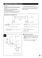
Keyboard Stand Assembly (DGX-500 only), DGX-500 only
 |
View all Yamaha DGX-500 manuals
Add to My Manuals
Save this manual to your list of manuals |
Page 105 highlights
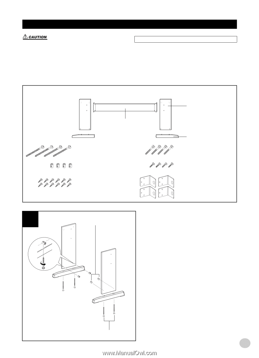
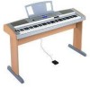
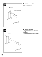
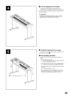
Keyboard Stand Assembly (DGX-500 only) • Be careful not to confuse parts, and be sure to install all parts in the correct direction. Please assemble in accordance with the sequence given below. • Assembly should be carried out by at least two persons. • Be sure to use the correct screw size, as indicated above. Use of incorrect screws can cause damage. • Be sure to tighten all screws upon completing assembly of each unit. • To disassemble, reverse the assembly sequence given below. Have a phillips-head (+) screwdriver ready. The parts shown in the "Assembly Parts" illustration will be used. Follow the assembly instructions and select the parts as needed. I Assembly Parts (DGX-500 only) Side boards Back board q 6 x 70 mm round head screws (4 pcs.) Stand bases r 6 x 30 mm round head screws (4 pcs.) w Joint connectors (4 pcs.) t 5 x 16 mm round head screws (4 pcs.) e 3.5 x 16 mm tapping screws (12 pcs.) y Angle brackets (4 pcs.) 1 w Joint connectors Z Attach the stand bases. Making sure that the boards are facing the proper direction (the holes should face inside), insert the joint connec- tors w into the holes as shown. The joint connectors have been installed properly if you can see a plus mark on the connector. Attach the stand bases to the rear of the side boards, using the 6 x 70 mm round head screws q. q 6 x 70 mm round head screws 105
-
 1
1 -
2
-
3
-
4
-
5
-
6
-
7
-
8
-
9
-
10
-
11
-
12
-
13
-
14
-
15
-
16
-
17
-
18
-
19
-
20
-
21
-
22
-
23
-
24
-
25
-
26
-
27
-
28
-
29
-
30
-
31
-
32
-
33
-
34
-
35
-
36
-
37
-
38
-
39
-
40
-
41
-
42
-
43
-
44
-
45
-
46
-
47
-
48
-
49
-
50
-
51
-
52
-
53
-
54
-
55
-
56
-
57
-
58
-
59
-
60
-
61
-
62
-
63
-
64
-
65
-
66
-
67
-
68
-
69
-
70
-
71
-
72
-
73
-
74
-
75
-
76
-
77
-
78
-
79
-
80
-
81
-
82
-
83
-
84
-
85
-
86
-
87
-
88
-
89
-
90
-
91
-
92
-
93
-
94
-
95
-
96
-
97
-
98
-
99
-
 100
100 -
 101
101 -
 102
102 -
 103
103 -
 104
104 -
 105
105 -
 106
106 -
 107
107 -
 108
108 -
 109
109 -
 110
110 -
111
-
112
 |
 |