Yamaha EMX5000-20 Owner's Manual
Yamaha EMX5000-20 Manual
 |
View all Yamaha EMX5000-20 manuals
Add to My Manuals
Save this manual to your list of manuals |
Yamaha EMX5000-20 manual content summary:
- Yamaha EMX5000-20 | Owner's Manual - Page 1
Owner's Manual Keep This Manual For Future Reference. E - Yamaha EMX5000-20 | Owner's Manual - Page 2
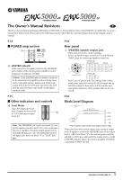
you for purchasing the Yamaha EMX5000-20/EMX5000-12 Powered Mixer. Parts of the EMX5000-20, EMX5000-12 owner's manual have been revised. Please refer to the following revisions rather than the corresponding sections of the original owner's manual. P.14 ■ POWER amp section X X LIMITER indicator - Yamaha EMX5000-20 | Owner's Manual - Page 3
EMX5000-20/EMX5000-12 CH INPUT A [-60~-16dB] [-34~+10dB] EMX5000-12:CH1-8 EMX5000-20:CH1-16 B CH INSERT I/O [0dB] EMX5000-12:CH1-8 EMX5000-20:CH1-16 +48V PHANTOM 8CH/SW EMX5000-12:[CH1-8] EMX5000-20 POWER AMP IN [+4dB] B YAMAHA SPEAKER PROCESSING YSP YSP MAIN 4dB] EFFECT SEND1 [+4dB] EFFECT SEND2 - Yamaha EMX5000-20 | Owner's Manual - Page 4
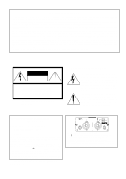
try to eliminate the problem by using one of the following measures: Relocate either this product or the device that is being affected by the interference. Utilize power outlets that are on different branch (circuit breaker or fuse) circuits or install AC line filter/s. In the case of radio or TV - Yamaha EMX5000-20 | Owner's Manual - Page 5
be damaged, turn the power switch off, remove the power plug from the AC outlet, and contact your dealer. If you continue using the unit without heeding this instruction, fire or electrical shock when cleaning the unit, remove the power plug from the AC outlet. EMX5000-20/EMX5000-12-Owner's Manual - Yamaha EMX5000-20 | Owner's Manual - Page 6
. Replacing abrasive parts • The performance Using a cell phone (mobile telephone) near this unit may induce noise. If noise occurs, use circuits of this unit may induce a slight noise into nearby radios and TVs. If noise occurs, relocate the affected equipment. EMX5000-20/EMX5000-12-Owner's Manual - Yamaha EMX5000-20 | Owner's Manual - Page 7
hall sound system 24 As a band PA 26 Using a subwoofer 28 Troubleshooting 29 Specifications 30 General specifications 30 Input specifications 31 Output specifications 31 Dimensions 32 Installing an optional rack mount kit 32 Block/Level Diagram 33 EMX5000-20/EMX5000-12-Owner's Manual - Yamaha EMX5000-20 | Owner's Manual - Page 8
the EMX5000-20/EMX5000-12. • When connecting a Speakon connector to the EMX5000-20/EMX5000-12, be sure to turn the plug to the right to lock the connection after inserting the plug. EMX5000-20/EMX5000-12-Owner's Manual EMX5000-20 (EMX5000-12) Power amp select switch • This quick guide explains - Yamaha EMX5000-20 | Owner's Manual - Page 9
EMX5000-20/EMX5000-12 Quick Guide 7 Connecting a microphone Make sure that the power is turned off to the EMX5000-20/EMX5000-12. Connect mics to channels 1-16 (EMX5000-20) or 1-8 (EMX5000-12), using the INPUT A jacks if the mic has an XLR plug, or the INPUT B jacks if the mic has a phone plug. - Yamaha EMX5000-20 | Owner's Manual - Page 10
EMX5000-20 (EMX5000-12) EMX5000-20 (EMX5000-12) • Be sure to follow the power up sequence specified above to prevent the speakers from being damaged. • To correct the low range, turn on the YAMAHA SPEAKER PROCESSING switch in the upper right corner of the panel. EMX5000-20/EMX5000-12-Owner's Manual - Yamaha EMX5000-20 | Owner's Manual - Page 11
lights up. 1 EMX5000-20 (EMX5000-12) 2 4 If you want to use effect channel 1, adjust the effect depth by turning the EFF1 control of the channel to which you want to apply the effect. EMX5000-20 (EMX5000-12) 4 STEP 5 Power off 1 Press the POWER switch of the EMX5000-20/ EMX5000-12 to turn off the - Yamaha EMX5000-20 | Owner's Manual - Page 12
you can adjust equalization (frequency response), volume level, effect and AUX output levels for the input signal of each channel. 1 2* 2 3 4 4 5 5 6 the mid range, use the upper MID knob to specify the center frequency of the range, and use the lower knob EMX5000-20/EMX5000-12-Owner's Manual - Yamaha EMX5000-20 | Owner's Manual - Page 13
will be affected not only by the setting of the EFFECT 1, 2 control, but also by the setting of the channel fader C (post-fader send). 7 PAN (panpot) control (EMX5000-20: Channels 1-16, EMX5000-12: Channels 1-8) The PAN knobs set the stereo position of the signal that is sent to the STEREO bus - Yamaha EMX5000-20 | Owner's Manual - Page 14
the AUX 1 bus to the AUX SEND 1 jack (input/output panel 8). If the Power amp select switch Y is set to AUX 1-MONO, using this fader enables you to adjust the level of the signal sent from the SPEAKERS A 1/2 ST control M to the PHONES jack (input/output panel D). EMX5000-20/EMX5000-12-Owner's Manual - Yamaha EMX5000-20 | Owner's Manual - Page 15
is on, the signal from before the EFFECT 1/2 RTN faders U will be sent to the PHONES jack (input/output panel D). U EFFECT 1/2 RTN fader This fader adjusts the level of the return signal that is sent from the built-in digital effect to the STEREO bus. U U EMX5000-20/EMX5000-12-Owner's Manual - Yamaha EMX5000-20 | Owner's Manual - Page 16
sent to the built-in two-channel power amplifier. X Y Z X LIMITER indicator This indicator lights up when the level of the signal output from the power amp section reaches the maximum and + 100W The two internal amps will produce a maximum of 100W + 100W/4Ω. EMX5000-20/EMX5000-12-Owner's Manual - Yamaha EMX5000-20 | Owner's Manual - Page 17
indicator This indicator will light up when the power of the EMX5000-20/EMX5000-12 is turned on. [ s Other indicators and controls ` s YAMAHA SPEAKER PROCESSING \ ON/OFF switch This switch enables you to compensate the low range of the speakers. The low range balance when this switch is - Yamaha EMX5000-20 | Owner's Manual - Page 18
is not possible to simultaneously use both the INPUT A and B inputs of a given channel. For each channel, use only one of the inputs as appropriate for the input source. Phantom power is switched on/off simultaneously for channels 1-8 and 9-16 (EMX500020), 1-8 (EMX5000-12). For this reason, devices - Yamaha EMX5000-20 | Owner's Manual - Page 19
selected by the AFL switches. The nominal output is 3mW when headphones are connected. E FOOT SW EFFECT 2 ON/OFF jack A separately sold Yamaha FC5 foot switch can be connected to this jack so you can use your foot to switch the built-in digital EFFECT 2 on/off. EMX5000-20/EMX5000-12-Owner's Manual - Yamaha EMX5000-20 | Owner's Manual - Page 20
/off the power to the EMX5000-20/EMX5000-12. Note: Before you turn the power of the EMX5000-20/EMX5000-12 on or off, the faders and controls in the master section of the control panel must be lowered to the minimum position. 3 SPEAKERS (speaker output) jacks These jacks are used to connect speakers - Yamaha EMX5000-20 | Owner's Manual - Page 21
you are using. When the power amp select channel connections Use speakers with an impedance in the range of 4-8 ohms if you are connecting only one speaker to each set of outputs. A maximum output of 500W + 500W will be obtained when 4-ohm speakers are used. EMX5000-20/EMX5000-12-Owner's Manual - Yamaha EMX5000-20 | Owner's Manual - Page 22
speakers are used. Two-channel connection Two-channel parallel using a bridge connection, do not connect a speaker to the B or A 2 jack. Bridge connection No connection No connection * Use the 1+(+) and 2+(-) pins of the 1 jack. 8Ω-16Ω Main Speaker EMX5000-20/EMX5000-12-Owner's Manual - Yamaha EMX5000-20 | Owner's Manual - Page 23
the rear panel. If more speaker outputs are needed, use the ST SUB OUT jacks and the MONO OUT jack. Power amplifier Power amplifier Headphones Power amplifier To add monitor speakers To add main speakers To add a subwoofer Additional/alternative PA system EMX5000-20/EMX5000-12-Owner's Manual - Yamaha EMX5000-20 | Owner's Manual - Page 24
appropriate INPUT A/B jacks (EMX5000-20: channels 1-16, EMX5000-12: channels 1-8) or the 17L/ 18R, 19L/20R (EMX5000-20), 9L/10R, 11L/12R (EMX5000-12) jacks. Note: You cannot use channel 1-16 (EMX5000-20), 1-8 (EMX5000-12) INPUT A and B jacks at the same time. 3 Turn on the power to the peripheral - Yamaha EMX5000-20 | Owner's Manual - Page 25
. Adds a sense of pitch to the tone. Effective on sounds that contain numerous overtones. The well-known effect used to distort the sound. This effect sets the delay time to the interval at which can not blink any faster than an interval of 256 ms (234.3 bpm). EMX5000-20/EMX5000-12-Owner's Manual - Yamaha EMX5000-20 | Owner's Manual - Page 26
. As a conference/entertainment hall sound system Here is an example of using the EMX5000-20/EMX5000-12 as a conference or entertainment hall sound system. Main speakers Microphone CD player Cassette deck (for paly back) Cassette deck (for recording) EMX5000-20/EMX5000-12-Owner's Manual - Yamaha EMX5000-20 | Owner's Manual - Page 27
switch to ST L-R. s Playing back a CD player 1 Turn on the power to the peripheral devices, then to the EMX5000-20/ EMX5000-12. 2 Start playback on the CD player. Use the GAIN control of channel 17/18 (EMX5000-20), 9/10 (EMX5000-12) so that the PEAK indicator below the GAIN control will light - Yamaha EMX5000-20 | Owner's Manual - Page 28
is independent of the MAIN speaker mix. An external effect such as delay or reverb is also being used. Main speakers Monitor speakers Microphone * Direct box, D.I.* effect unit, pre-amp, etc. Effect unit Bass guitar Guitar 88 Effect processor Keyboard EMX5000-20/EMX5000-12-Owner's Manual - Yamaha EMX5000-20 | Owner's Manual - Page 29
, such as keyboards, to channel input jacks 1-20 (EMX5000-20), 1-12 (EMX5000-12). • Connect the main speakers to the SPEAKERSB 1/ 2 jacks, and connect the monitor speakers to the SPEAKERS A 1/2 jacks. Set the Power amp select switch to "AUX 1-MONO." • If you use an external effect such as delay or - Yamaha EMX5000-20 | Owner's Manual - Page 30
switch (located in the lower right of the EMX5000-20/ EMX5000-12) to send the low-range signal to the sub-woofer. The frequency range below the frequency specified by the control knob (80-120 Hz) will be output to the sub-woofer. Main speakers Power AMP Subwoofer EMX5000-20/EMX5000-12-Owner's Manual - Yamaha EMX5000-20 | Owner's Manual - Page 31
SUB INPUT section may not be rotated to right. A: The AUX controls for input channels may not have been adjusted. A: You cannot use the INPUT A jack and the INPUT B jack for the same channel at the same time. A: Yes. Use a speaker with an impedance of 4-8 ohms. EMX5000-20/EMX5000-12-Owner's Manual - Yamaha EMX5000-20 | Owner's Manual - Page 32
control, foot switch (DIGITAL EFFECT ON/OFF, TAP) Digital effect 2 mute: on/off, Tap delay POWER switch on/off mute, DC detection, TEMP (heatsink temp. ≥90°C) stop - low speed (50°C) - variable - high speed (70°C) +48 V (balanced input) FC5 (Foot switch), RK-124 (EMX5000-12) USA and Canada:120 - Yamaha EMX5000-20 | Owner's Manual - Page 33
Input specifications 31 Dimensions (WxHxD) Weight Accessories 682 × 158 × 538 mm (EMX5000-20) / 478 × 158 × 538 mm (EMX5000-12) 19 kg (EMX5000-20) / 15 kg (EMX5000-12) Power cord, Owner's Manual s Input specifications Input terminals Gain control Actual load impedance For use with nominal - Yamaha EMX5000-20 | Owner's Manual - Page 34
Specifications Dimensions 682 (EMX5000-20) 478 (EMX5000-12) 143 158 538 Specifications are subject to change without prior notice. Unit: mm s Installing an optional rack mount kit By using the RK124 rack mount kit, you can install the EMX5000-12 in a rack. Before you rack-mount the EMX5000-20 - Yamaha EMX5000-20 | Owner's Manual - Page 35
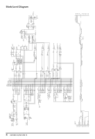
DR PEAK DR MONO OUT [+4dB] A POWER AMP IN [+4dB] B YAMAHA SPEAKER PROCESSING YSP YSP MAIN L AUX1 AUX1 MONO BRIDGE INV Signal Select MAIN ] AUX SEND2 [+4dB] EFFECT SEND1 [+4dB] EFFECT SEND2 [+4dB] PHONES [3mW@40ohms] Block/Level Diagram 33 EMX5000-20/EMX5000-12-Owner's Manual 0dB=0.775V 0dBV=1V - Yamaha EMX5000-20 | Owner's Manual - Page 36
- Yamaha EMX5000-20 | Owner's Manual - Page 37
- Yamaha EMX5000-20 | Owner's Manual - Page 38
V821290 R0 1 AP 36 NP Printed in Taiwan YAMAHA CORPORATION Pro Audio & Digital Musical Instrument Division P.O. Box 3, Hamamatsu, 430-8651, Japan
-
 1
1 -
 2
2 -
 3
3 -
 4
4 -
 5
5 -
 6
6 -
 7
7 -
8
-
9
-
10
-
11
-
12
-
13
-
14
-
15
-
16
-
17
-
18
-
19
-
20
-
21
-
22
-
23
-
24
-
25
-
26
-
27
-
28
-
29
-
30
-
31
-
32
-
33
-
34
-
35
-
36
-
37
-
38
 |
 |
Owner’s Manual
E
Keep This Manual For Future Reference.